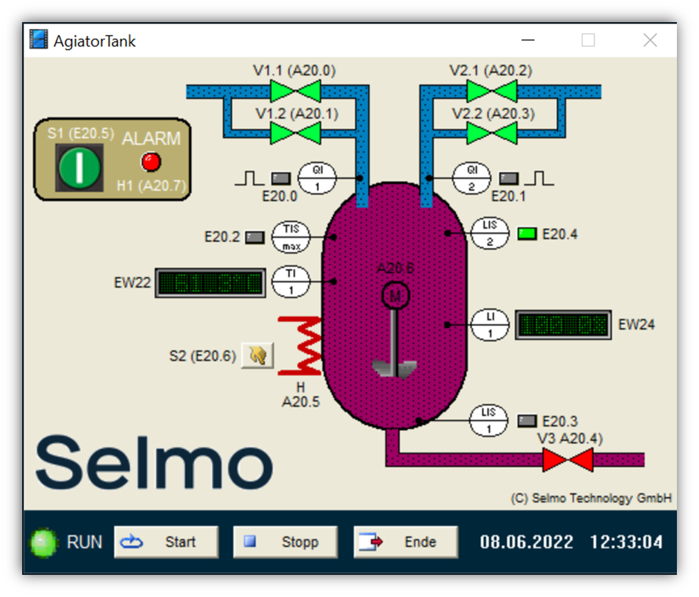
The mixing tank model consists of a tank with a motor-driven agitator M, in which two liquids are mixed together in a predetermined ratio and then heated to a target temperature. The two liquids are supplied via two feed lines, both have a coarse valve (V1.1 or V2.1) and a fine valve (V1.2 or V2.2) for precise metering. The two flow rate sensors QI1 and QI2 generate pulses which frequency is proportional to the respective filling speed; one impulse corresponds to just 1% of the container volume. The outflow of the mixture is controlled via valve V3. Two limit value transmitters (LIS1 / LIS2) and an analog value transmitter (LI1) are available for measuring the level. The liquid in the tank can be heated by a heatingelemt H; A limit value transmitter (TISmax) and an analog value transmitter (TI1) are available for measuring the temperature. The heating can be switched on program-controlled or manually using the S2 button. The alarm lamp H1 indicates that the temperature limit is exceeded. The mixing process is started with the start button S1.
Input / output assignment
The inputs and outputs of the model are assigned as follows. (The designation input or output refers to
in each case on the connected controller):
Input No. Name TwinCAT-variable name Description
1 QI1 I_S1 Impulse flow rate transmitter left inlet
2 QI2 I_S2 Impulse flow rate transmitter right inlet
3 TISmax I_B1 limit value transmitter temperature
4 TI1 I_B2 Analog value transmitter temperature in degrees (100 ° = 27648)
5 LIS1 I_S3 Lower limit indicator level
6 LIS2 I_B4 Upper limit indicator level
7 LI1 I_B5 Analog value transmitter level in% (100% = 27648)
8 S1 I_B6 Start button
9 S2 I_B6 Switch on the heating switch
Output No. Name TwinCAT-variable name Description
1 V1.1 O_Y1 Left inlet coarse valve
2 V1.2 O_Y2 Fine valve left inlet
3 V2.1 O_Y3 Right inlet coarse valve
4 V2.2 O_Y4 Fine valve right inlet
5 V3 O_Y5 Valve drain
6 H O_Y6 Switch on the heating
7 M O_Y5 Motor agitator
8 H1 O_Y6 Alarm light