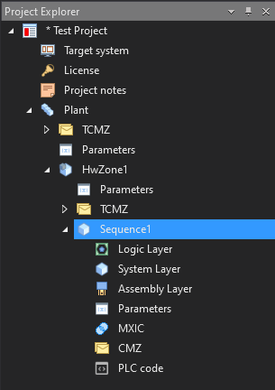
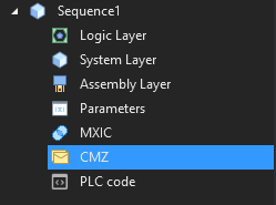
The sub-categories of the sequence are displayed in the Start page window.
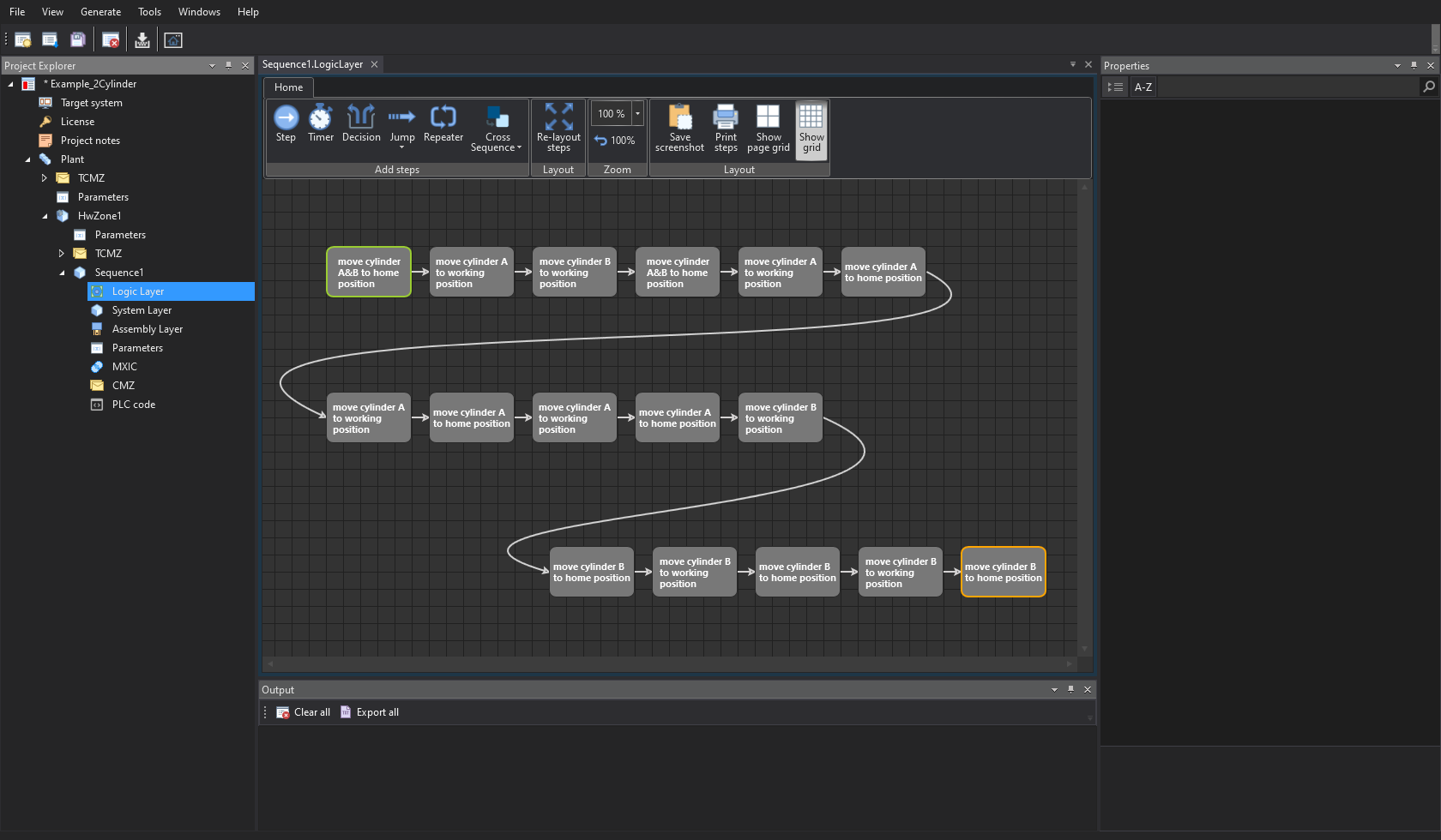
Logic Layer:
The logic layer is used to pre-model the steps of the model on a graphic surface.
This graphic representation makes modeling the process a lot easier.
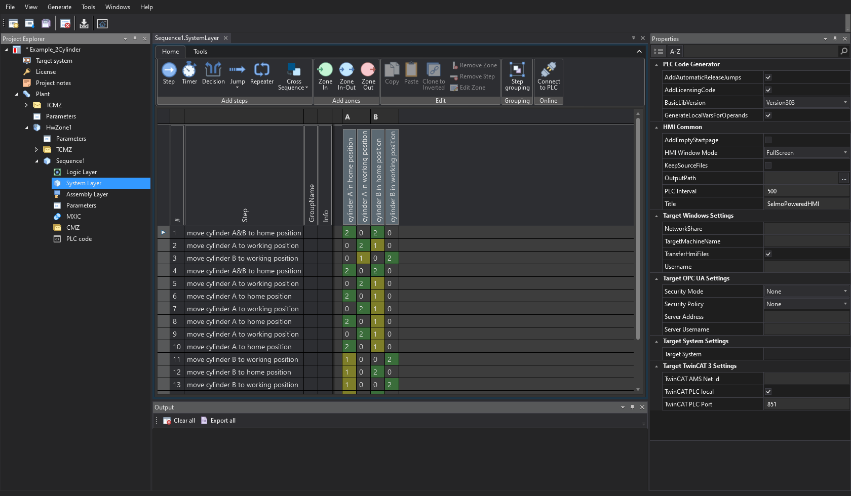
System Layer:
In this area the program is modeled, the steps as well as the zones are defined and the machine statuses or monitoring are defined.
The Selmostudio can also be connected to the PLC in order to follow the running program in real time.
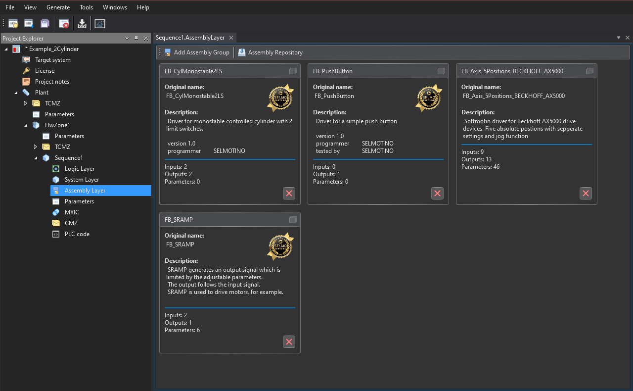
Assembly Layer:
In the Assembly Layer you can select or add drivers for your model.
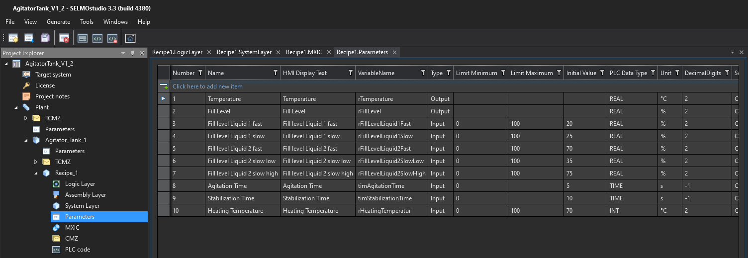
Parameters:
The Selmo standard has a parameter layer. The input and output data points are defined there. That makes the process flexible and adaptable.
Example: A saw that moves to a position and cuts where the position is reached. This is always the same procedure, but the position can be changed.
Or a drive with different speeds. All data in and out of the machine can be easily defined.
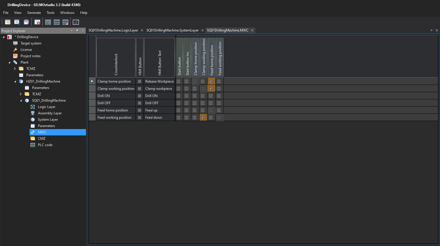
Manual Cross Interlock Check:
There is a final reason to ‘open’ a Sequence Zone. This is for Manual Cross Interlock Checks or M.X.I.C checks.
The purpose of the M.X.I.C check is to indicate why a manual operation will not occur, take for instance a Lift table which incorporates a Shot Pin, where the Shot Pin must be extracted before the Lift Table can raise.
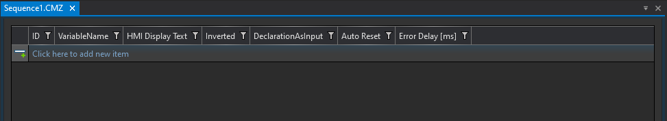
Constantly Monitored Zone
C.M.Z FAULT
Sequence Constantly Monitored Zone. The C.M.Z fault is a Flag within the standard end of the program which monitors the area of the Step Sequence fault matrix dedicated to machine unsafe conditions related to the individual sequence.
On detecting a C.M.Z Lamp Marker ON, the C.M.Z fault Flag energizes to immediately trip Automatic Release and therefore stop Automatic operation of the individual sequence.
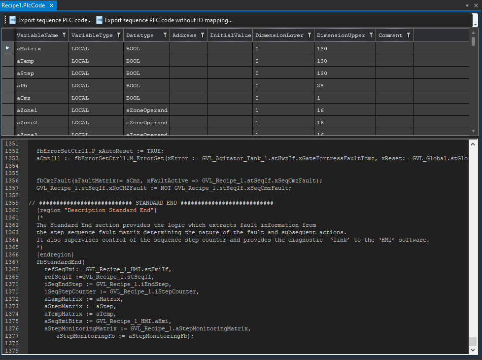
PLC code:
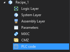
The code generator in the background generates the error-free PLC code and the HMI from the data of the model.
It is displayed in this window.