The automaton table describes the state transitions for the corresponding input vectors. The output vectors are directly dependent on the states and are also assigned to these in the representation. The automaton table is very similar to the ZZM and should therefore also be understood as a basis.
U1 = [E1]; U2=[E2]; U3=[E3];
Y1 = [A1]; Y2 = [A2];
Z1 = [Wait for button E3]; Z2 = [Move cylinder to position E2]; Z3 = [Wait for button E3];
Z4 = [Move cylinder to position E1]
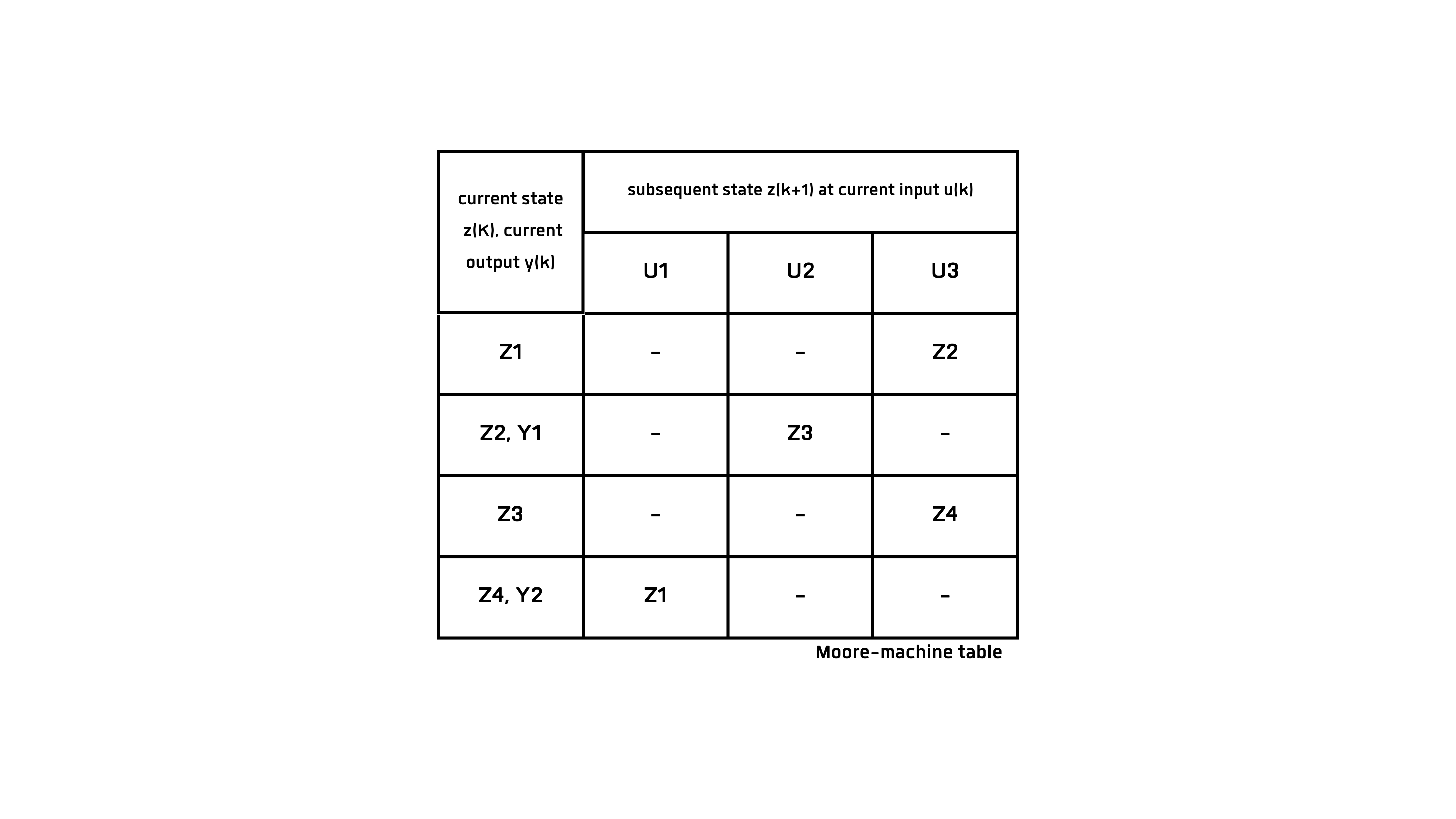
The automaton table is suitable for very large automata with many states. It is easy for people to see which subsequent state results from an input (Ux). And in which state which output (Yx) occurs. You can get a very good overview of whether the automaton is fully defined. This is the case if it can react to every input in every state. This means that there must not be a ( - ) at any point in the table. If a line of a state only contains a ( - ), this is a final state. This means that once this state has been reached, it cannot be exited with any input.