The machine table is extended in the ZZM by a few symbols so that the display on the MMI can also be modeled. It is not the entire input vectors that are considered, but the individual input signals. The signals E1 and E2 form a signal pair because they describe an actuator and can therefore only ever occur mutually. A signal pair can also be generated from signal E3. An additional zone is generated in which the signal E3 is queried to 0. This ensures that the transition is only carried out when button E3 is released.
In the table, the diagnostic behavior is assigned to the input signals according to the states. The states are shown in the row and the zones in the columns. This is where the term state-zone modeling comes from. Each input signal is assigned a matrix bit Mx and, if necessary, a pair check bit Px. The system is extended by the outputs Zx, Mx and Px, as these are used for status display on the MMI. The Zx outputs are intended to provide the operator with information about the current status, the following statuses and the statuses already passed through.
As described under point 4, this is a sequence control. The input signals from the control section are fed to the control unit via sensors and, together with the status of the control unit, produce the outputs by switching the states accordingly. The sequence is precisely specified, i.e. Z1 is switched to Z2 by fulfilling the defined transition conditions and so on.
In the table, input E1 and the two inputs E2 and E3 generate the zones. The target state of the input is determined by the state of the control device:
2 Here, the corresponding output is activated so that a signal change takes place and the associated matrix bit is set to 1 at the interface to the operator to indicate which input signal is expected.
1 The input signal must be set to 1 here, otherwise an error is diagnosed in the control path.
0 The "don't care" rule applies here.
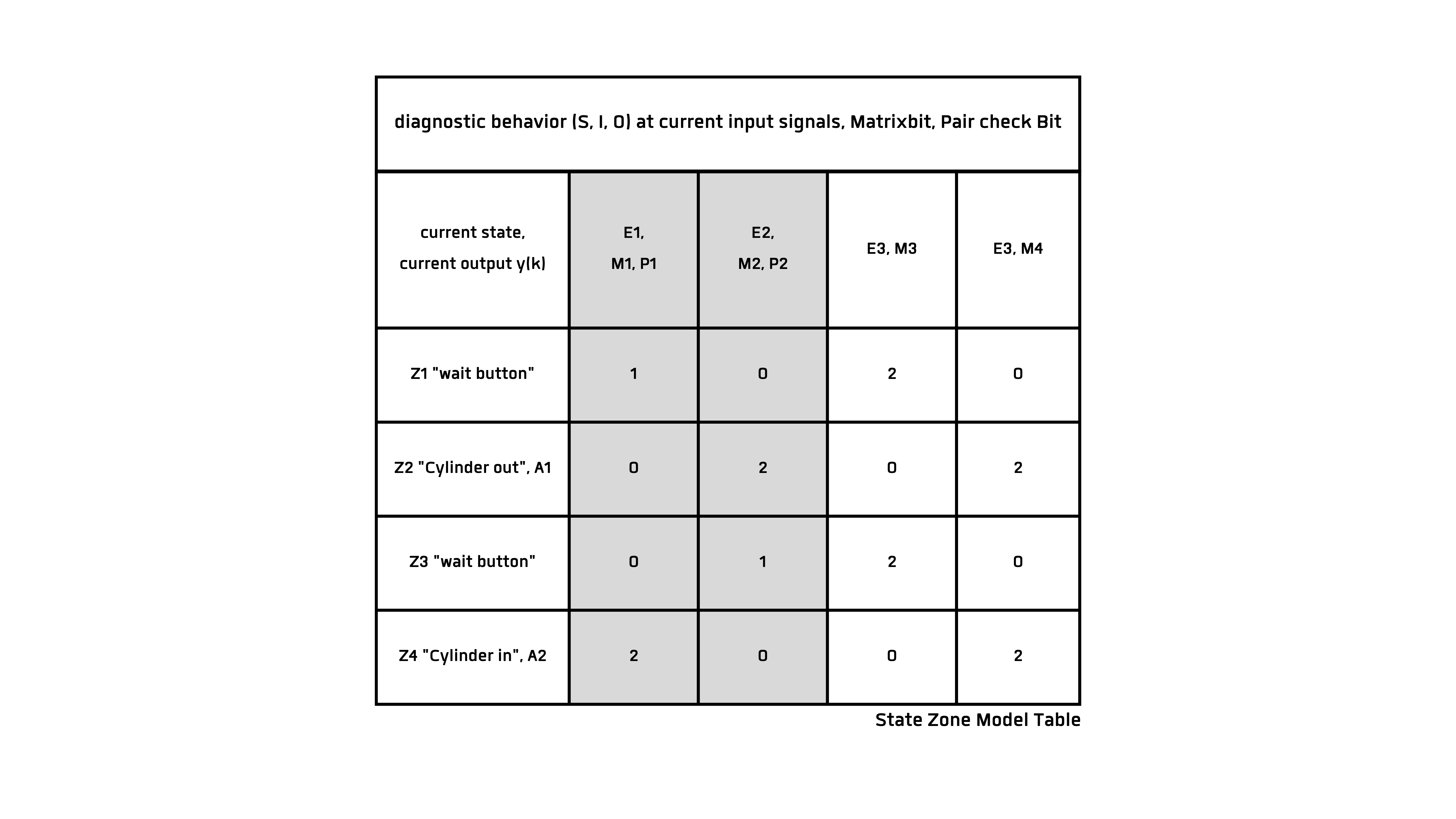
Inputs E1 and E2 are located on the cylinder and must therefore be treated as belonging together. The cylinder is always in one of the positions. Only during movement (defined as S) are none of these positions occupied. If the two inputs E1 and E2 occur simultaneously, an error state occurs in the control section. Such a unit (e.g. the cylinder) is checked for "pair check" and thus leads to an error state. This error is clearly indicated to the MMI by the Px at the interface to the operator.
Button E3 is also viewed in two contiguous zones. This achieves a defined status of the button in the Zx states. The pair check can be neglected, as in physical reality it is not possible for a signal to be 0 and 1 at the same time.
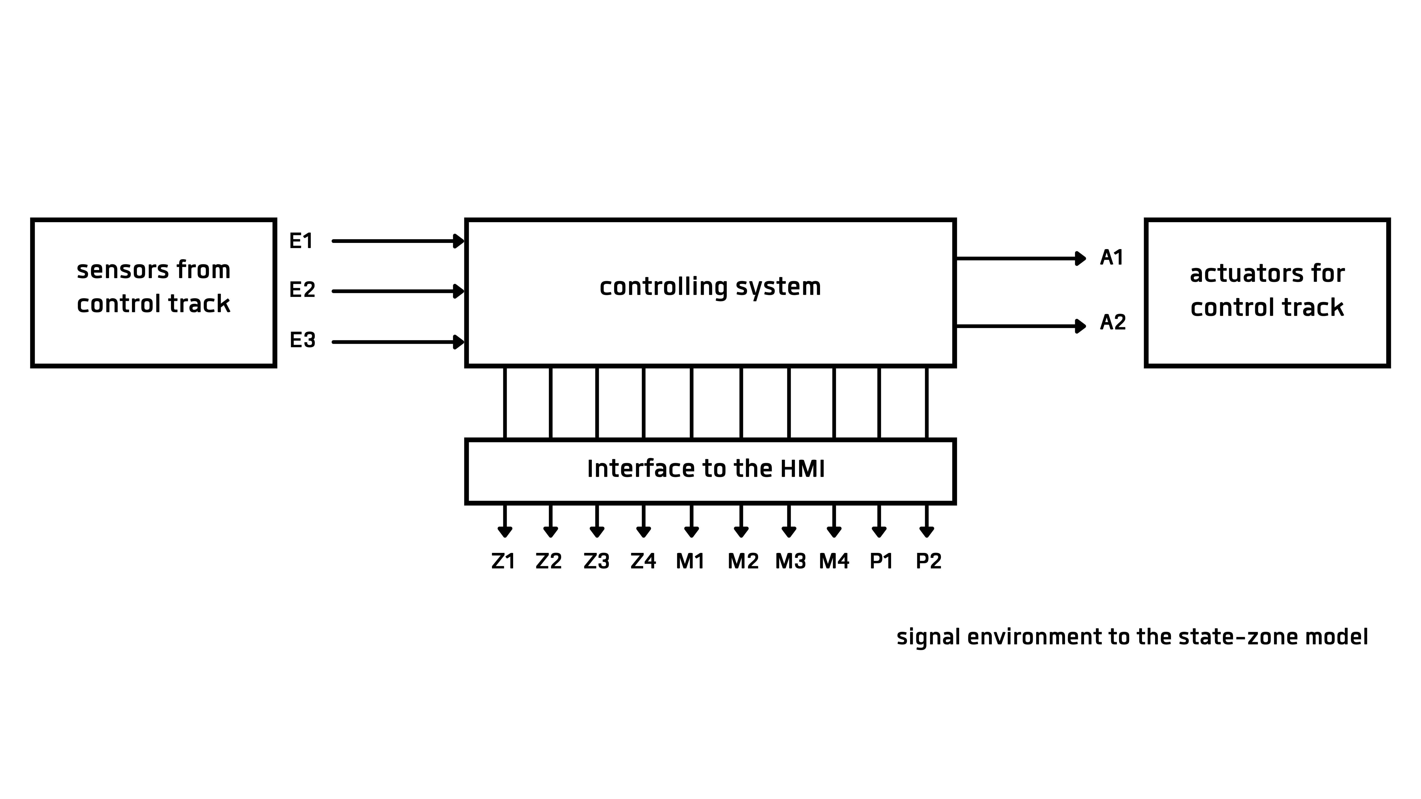
As shown in Figure 1-1, the operator's or user's view of the control system must also take into account the outputs to the user via the human-machine interface. This expands the outputs of the system and should always provide the user with the best possible information about the current status of the system. In the event of an error, the user must be informed of the cause of the error. This can only be guaranteed if the informal and formal specification is extended to include the user's perspective.