In the state-zone model, a matrix vector ![]() must be introduced. The output vector is not listed in the table, as the outputs A1 and A2 are each switched in the defined states. The inputs have no direct influence on the outputs. A forbidden state must be defined for the inputs E1 and E2. If both occur at the same time, there is definitely an error state in the control circuit.
must be introduced. The output vector is not listed in the table, as the outputs A1 and A2 are each switched in the defined states. The inputs have no direct influence on the outputs. A forbidden state must be defined for the inputs E1 and E2. If both occur at the same time, there is definitely an error state in the control circuit.
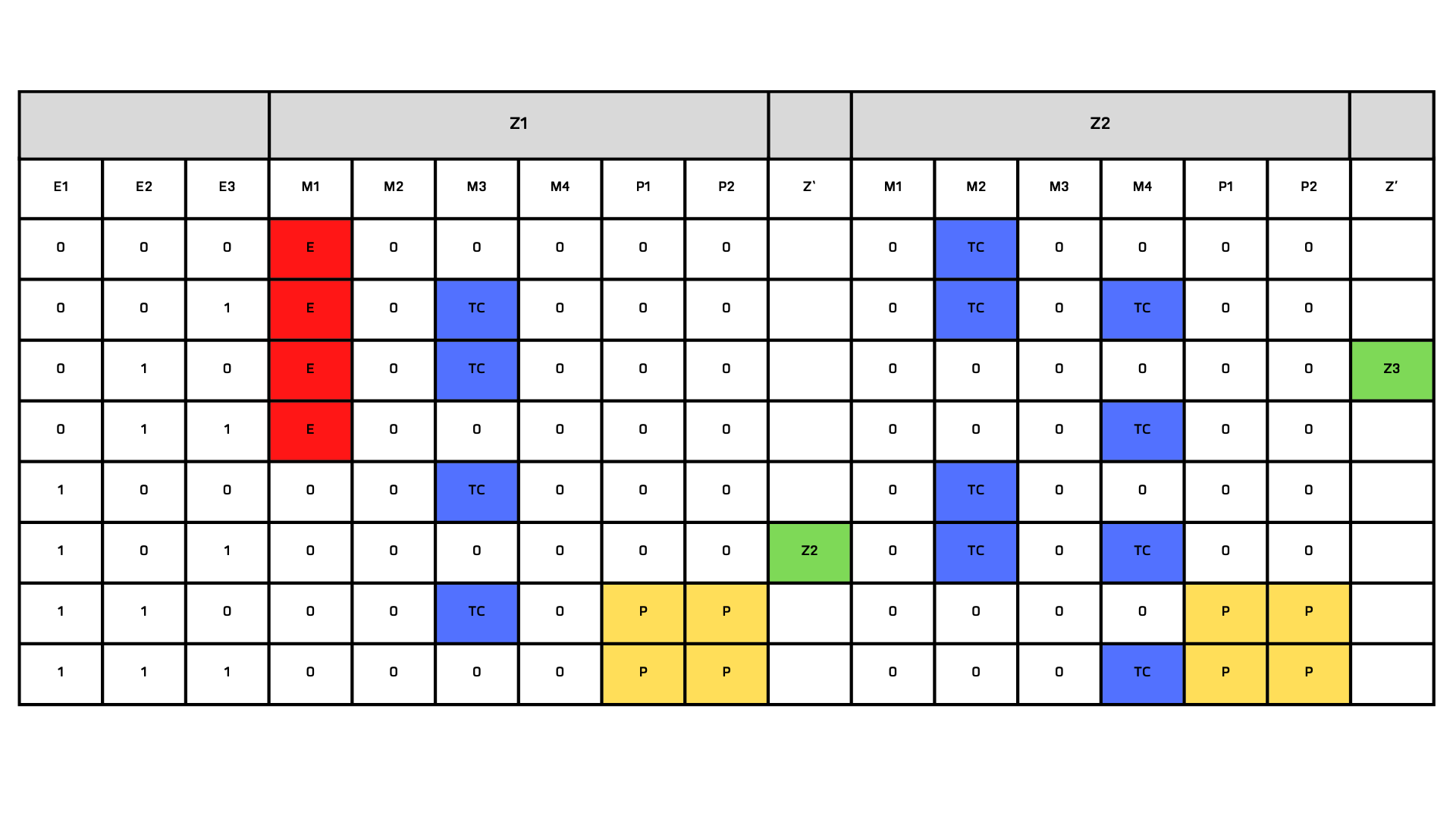
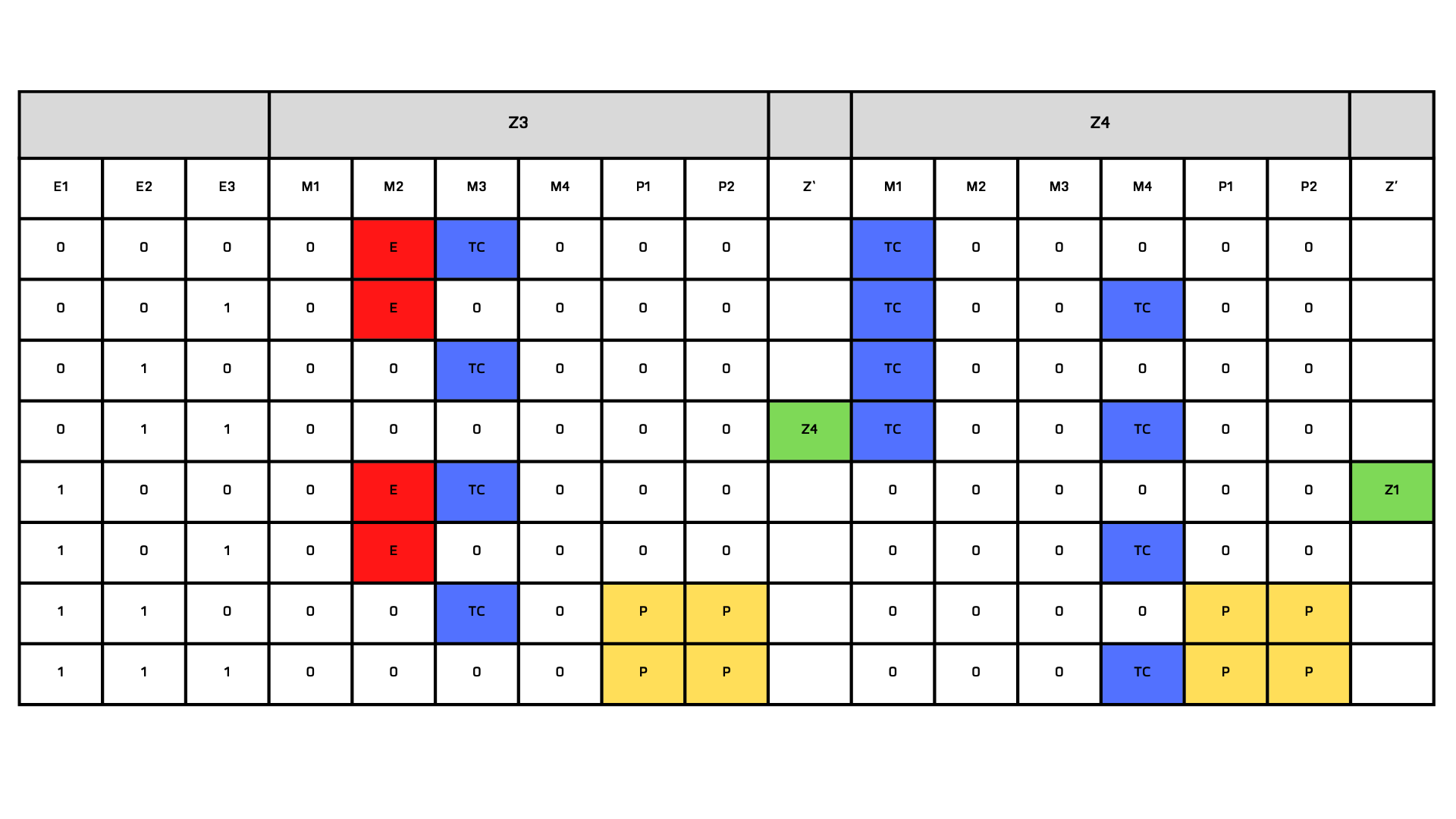
E... Error condition TC... Transition condition
P... Paircheck Zx... Next state Z'
Mx.. Message bit to the user interface
Z1 is defined as the initial state. Each input combination is transferable into a defined state.
The transitions are activated once. All defined states (Z1, Z2, Z3, Z4) are passed through.
Z1 is defined as the initial state. Each input combination is transferable to a defined state.
The transitions are activated once. All defined states (Z1, Z2, Z3, Z4) are passed through.
In the line in which a subsequent state Z' follows, as a result, the transition condition is fulfilled and leads to the next state.
In the line in which a transition condition (TC) follows, as a result, the system waits for the fulfilment of the transition condition. So that the operator is informed, this event is output on the HMI via the Mx signals.
In the line in which an error (E) follows, as a result, the system is brought to a general error state. By definition, this is the system state that no longer allows any automatic processes to be carried out. In a figurative sense, the automation of the machine or system would be cancelled and all outputs to the actuators would be reset. From this state, it is only possible to switch back to an automatic mode in a specific and defined way.
In the line where a pair check is a result, a message is generated on the HMI and the consequence is the same as for an error (E). Since this has resulted in an undefined state in the control section.
The state-zone model describes a control system in terms of state sequences and behaviour in its entirety. All possible input vectors produce a defined result. The functionality and reliability are thus given in the model. This statement can be confirmed by verification through the method of simulation.
In contrast to all the models shown, the state-zone model takes into account the modelling of the interface to the operator.