Step
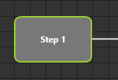
The step is the basic element for modeling, which is used to describe the individual discrete process steps or plant states. Each step is assigned a unique ID. A step is defined as an initial state with ID 1 via the "Start Shape" property.
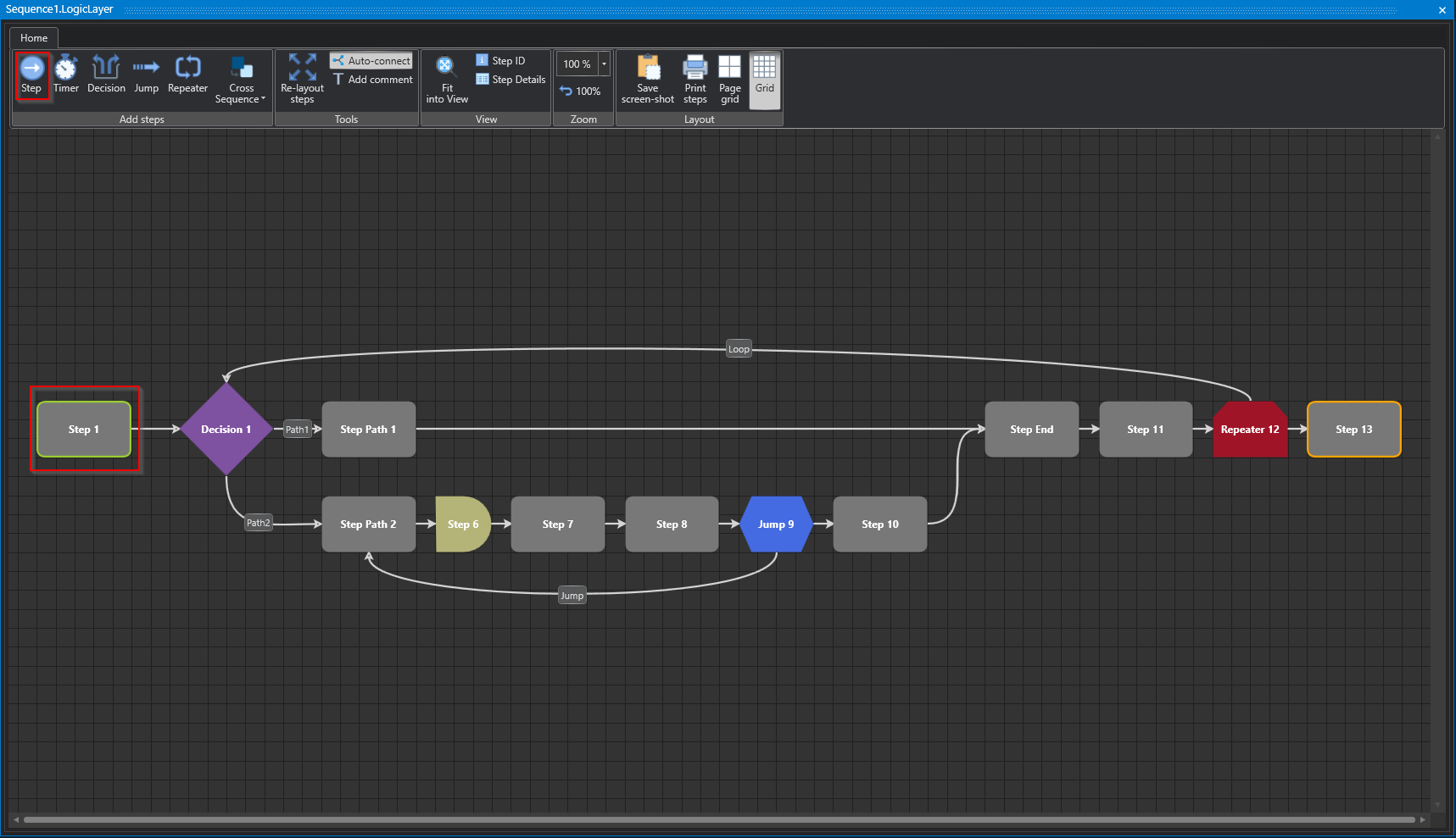
Studio
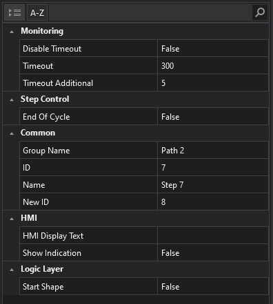
Properties
Studio
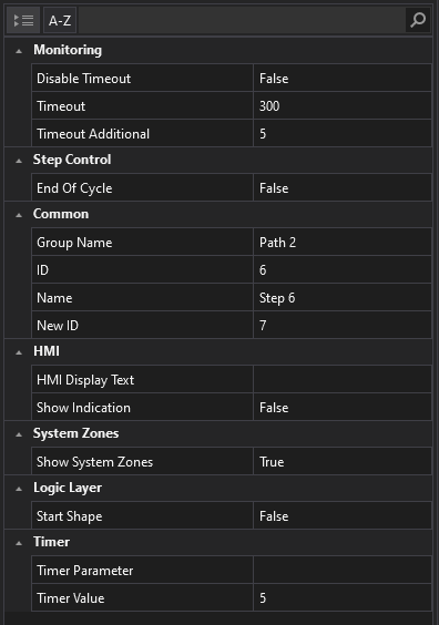
Monitoring
Step time monitoring is a function that monitors the execution time of each step in a program. It can be activated or deactivated via the HMI. The monitoring is "cycle-accurate", i.e. the time is measured in each cycle and compared with a preset limit value. If the time exceeds the limit value, an alarm is triggered. The step time monitoring is displayed in a window in the HMI, which shows the current time, the limit value, and the status of each step. An additional time can be defined, which is added to the measured time when determining the limit value. The step time alarm is triggered when the current step time exceeds the limit value formed by the measured step time plus the additional step time.
Disable Timeout
In this section you have the option to disable the step time monitoring for the selected step. Note, however, that step time monitoring is enabled by default.
Timeout
In the HMI (Human-Machine Interface), a warning is displayed if there is no change of state within a certain period. Please specify during which period, without a state change, a warning should appear on the HMI.
Timeout Additional
In teach mode, the step times can be measured, and this time will be added to the measured time. A warning will be issued on the HMI, if a step exceeds the measured time plus a specified tolerance time. Please note that the exact settings and parameters for measuring the step times, the tolerance time, and the warning on the HMI depend on the specific application or system and must be configured accordingly.
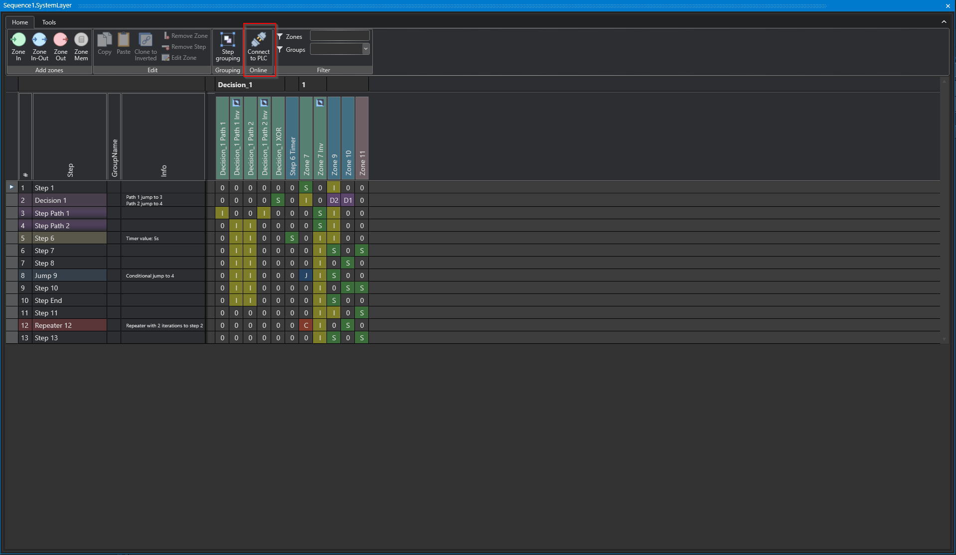
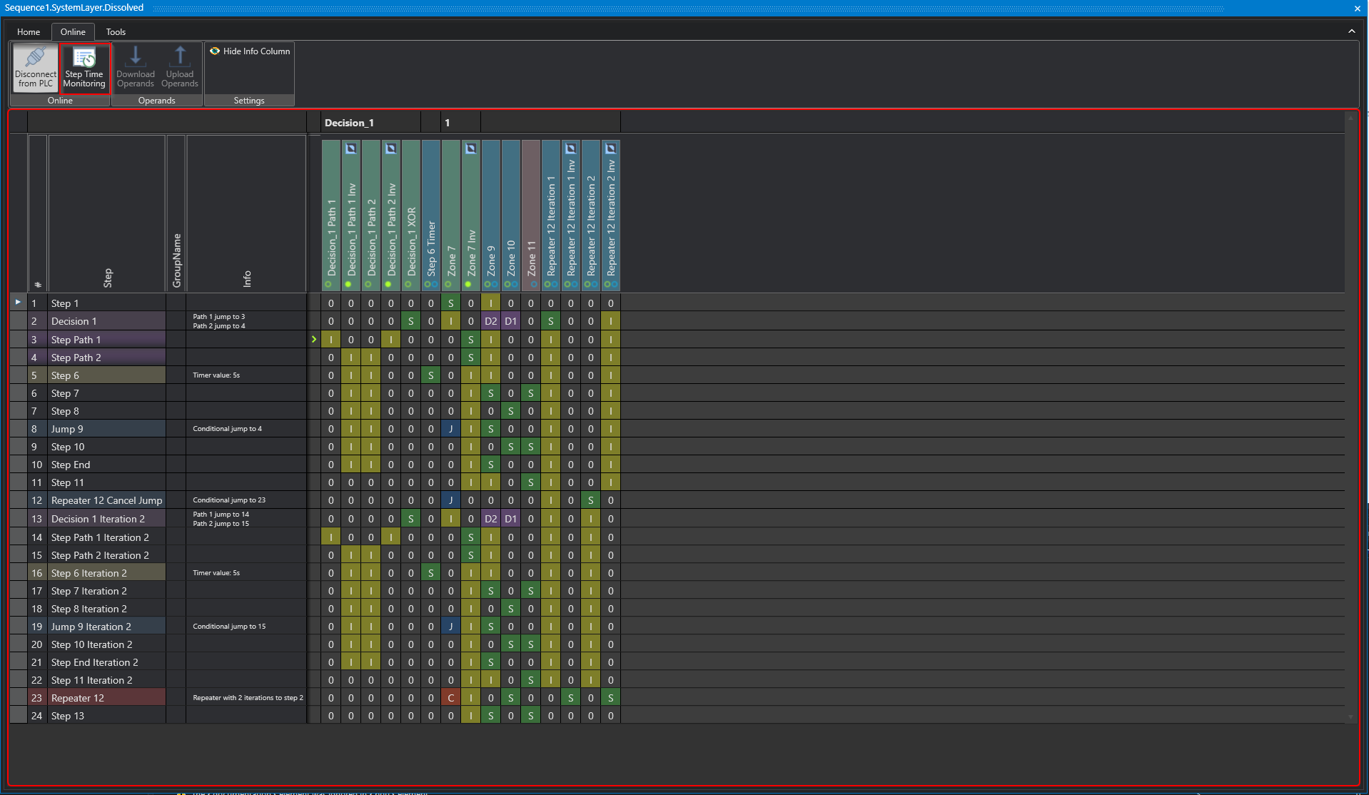
To access the online monitoring in the Studio in the System Layer, you can use the following icons:
Studio
Studio
At this point all step related data is displayed in different formats.
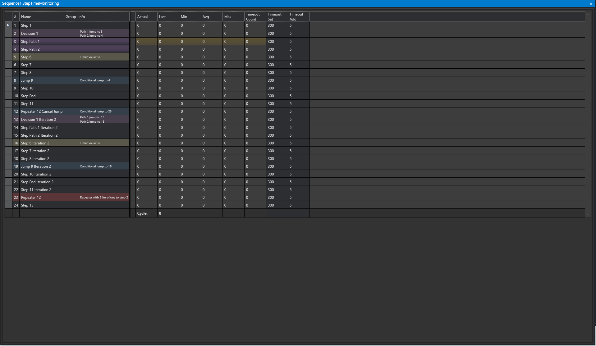
Studio
Step time monitoring is also available in the HMI.
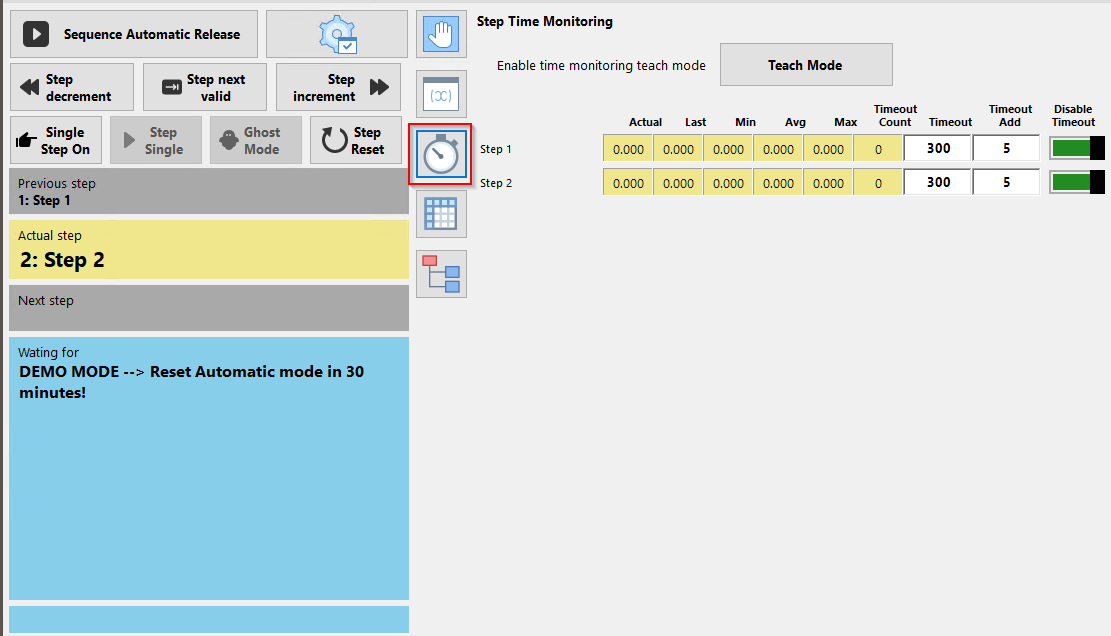
HMI
Step Control
End Of Cycle (EOC) is an operating mode that puts the plant in a safe state when production is finished. The plant runs until the defined EOC step is reached, which can vary depending on the plant type. The EOC mode can be safely switched on via the safety key switch on the operator console. The display on the HMI shows the current status of the EOC mode. Each Sequence has its own EOC step, which shuts down the corresponding components or moves them to a park position.
End Of Cycle
This setting can be used to specify that the sequence may safely stop at the specified step when stopped after the end of the cycle.
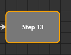
Studio
Common
Group Name
It is possible to group steps by a common group name.
ID
The step ID is the unique ID within a sequence, this is automatically assigned by the system depending on the start step.
Name
The name is displayed in the HMI layer as well as in the system layer. If no text has been entered for the "HMI Display Text" property, this name will be used instead.
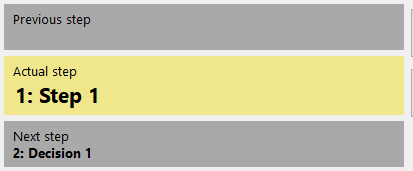
HMI
HMI
HMI Display Text
The "HMI Display Text" is the text that is displayed in the HMI for this step and can be used as an alternative to the name.

HMI
Logic Layer
Start Shape
Defines the first step of the sequence.
Studio
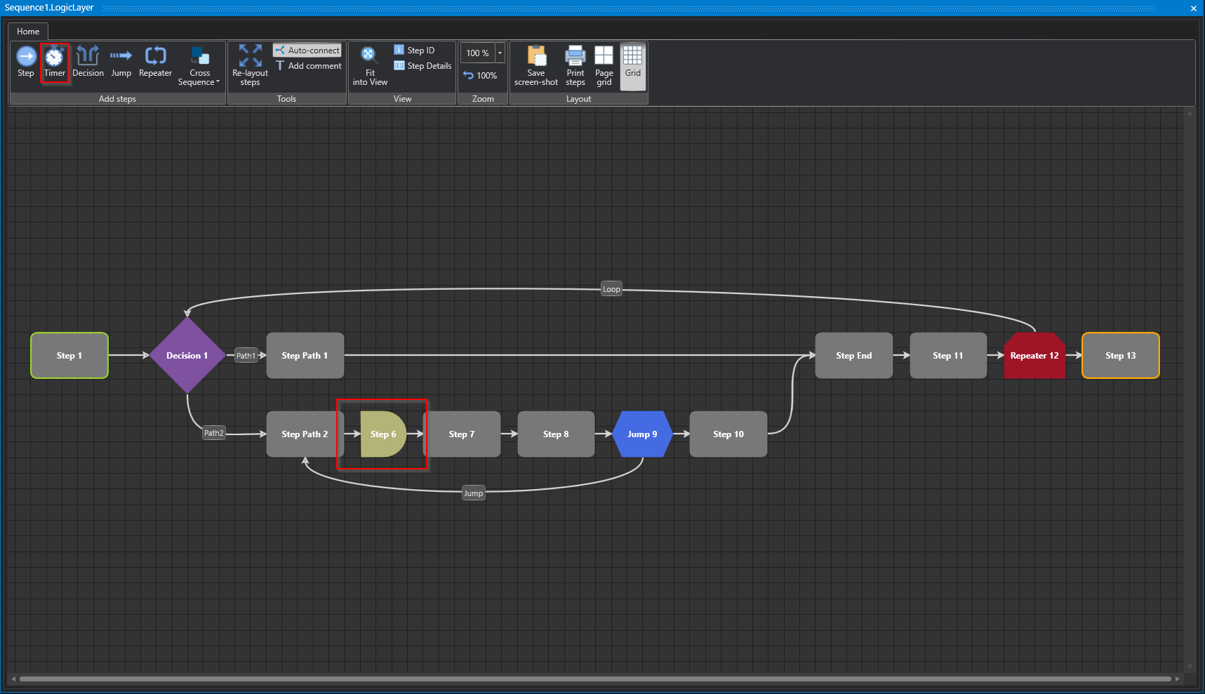
Timer Step
The Timer element allows the modeling of time-dependent steps. A timer step can only change to the following step when a specific time has elapsed. This time is specified by a timer parameter. An example would be a timed stirring process in a tank, where the step does not move to the next step until the predefined stirring time has elapsed.
Studio
Properties
Studio
System Zones
System Zones are the zones, automatically generated with a step and are essential for the step to function.
Show System Zones
It is possible to show or hide the system zones in the System Layer.
Timer
Timer Parameters
It is possible to use a parameter previously created in Parameters as a time base.
Timer Value
It is possible to enter a fixed time for this step.
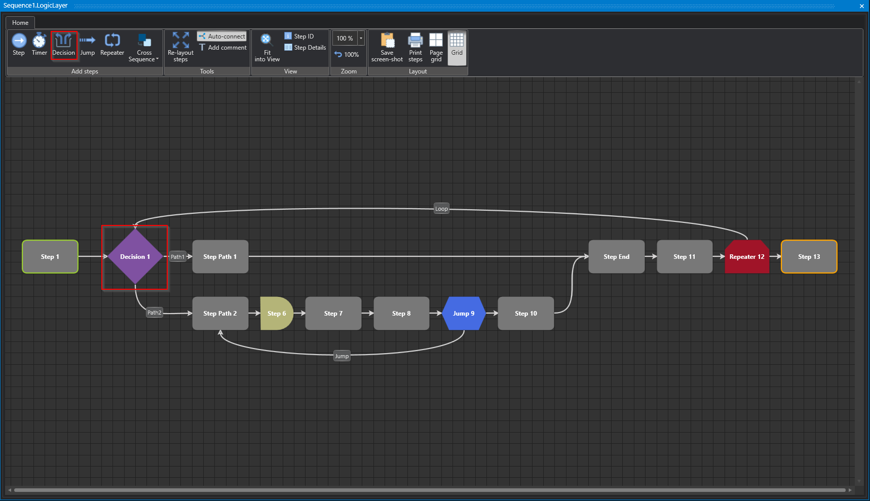
Decision Step
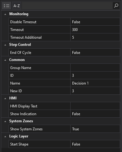
The Decision step is used to make decisions in the process. Depending on the fulfillment of a criterion, it is decided which path will be continued in the Sequence. Two paths can be selected, as shown in the figure below.
Studio
Properties
Studio
Jump Step
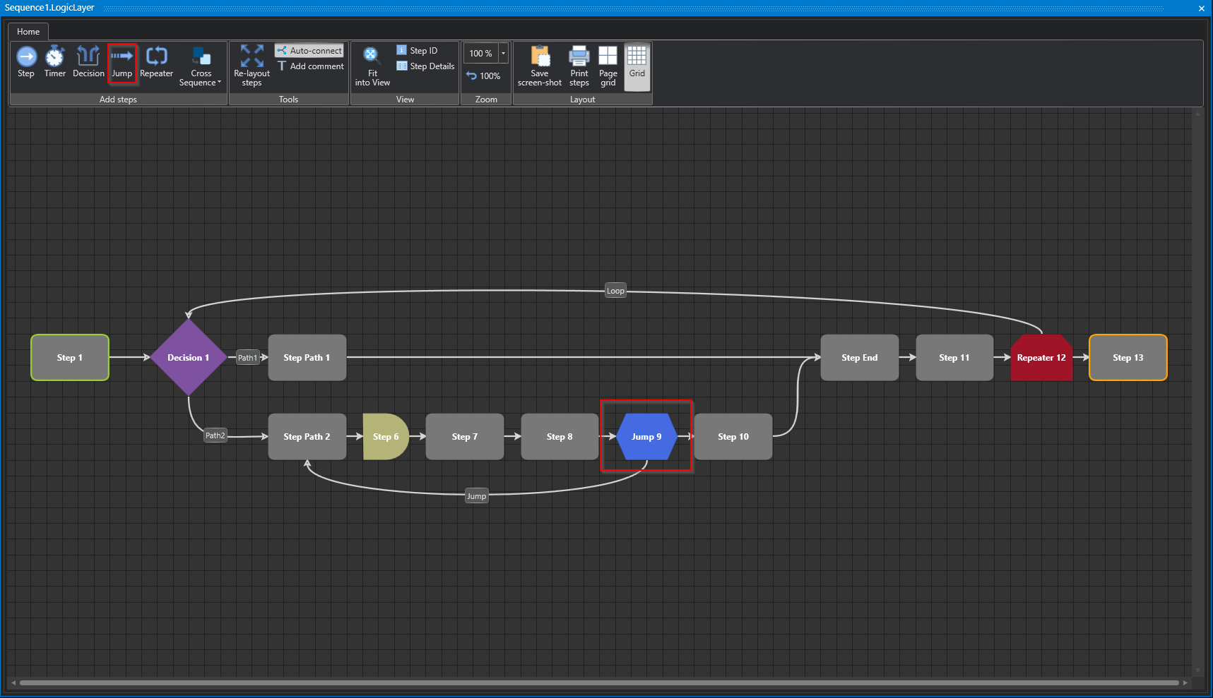
A jump in process modeling allows you to jump from a specific step to another step in the step chain to affect program flow. Jumps can be used to implement conditional flows or to skip or bypass certain steps based on special conditions or events. The use of jumps requires careful planning and modeling to ensure that the flow of the step chain works correctly and reliably. Improper use of jumps can lead to errors and make program logic unpredictable.
Studio
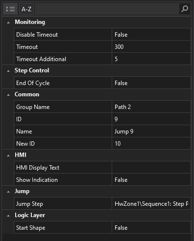
Properties
Studio
Jump
Jump Step
Determination of the jump target, i.e. the step to jump to, based on specific conditions stored in the system.
Repeater Step
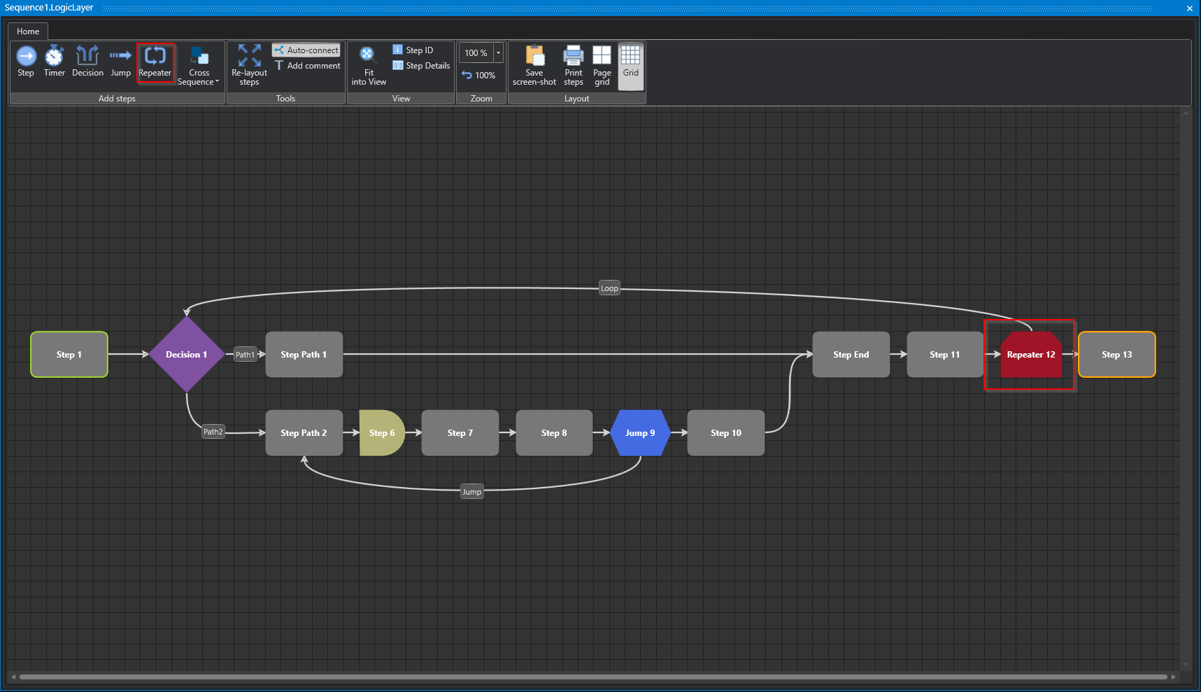
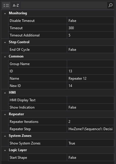
The repeater allows repeated execution of specific steps previously modeled by copying the steps defined in the loop up to the specified number of repeater iterations. This is a finite sequence of iterations rather than traditional loop programming. The repeater also provides the ability to terminate loop execution before reaching the maximum iteration by using a termination variable.
Studio
Properties
Studio
Repeater
Repeater Iterations
Determines the number of duplications of steps in the loop.
Repeater Step
Determines the target step to jump to.