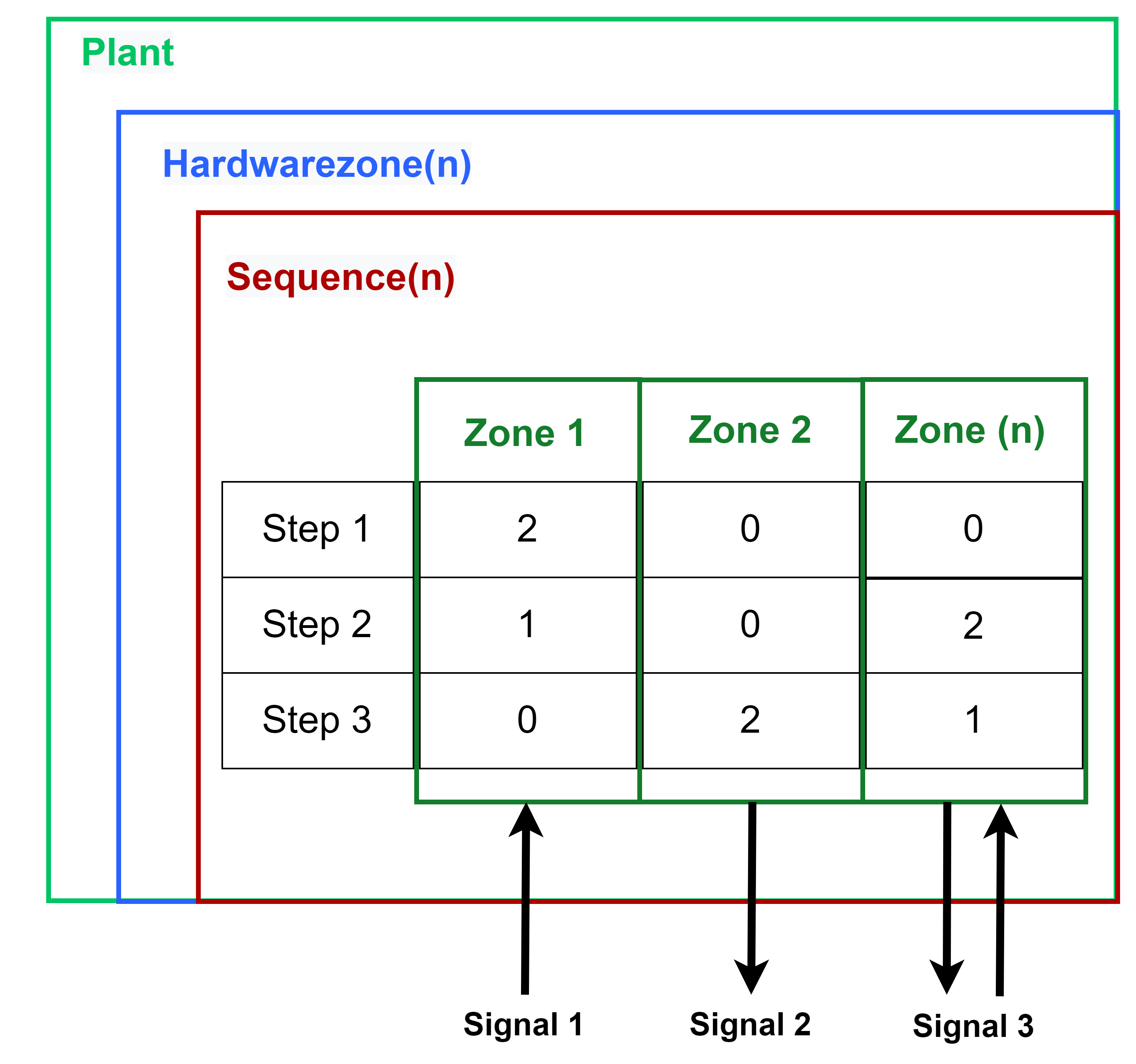
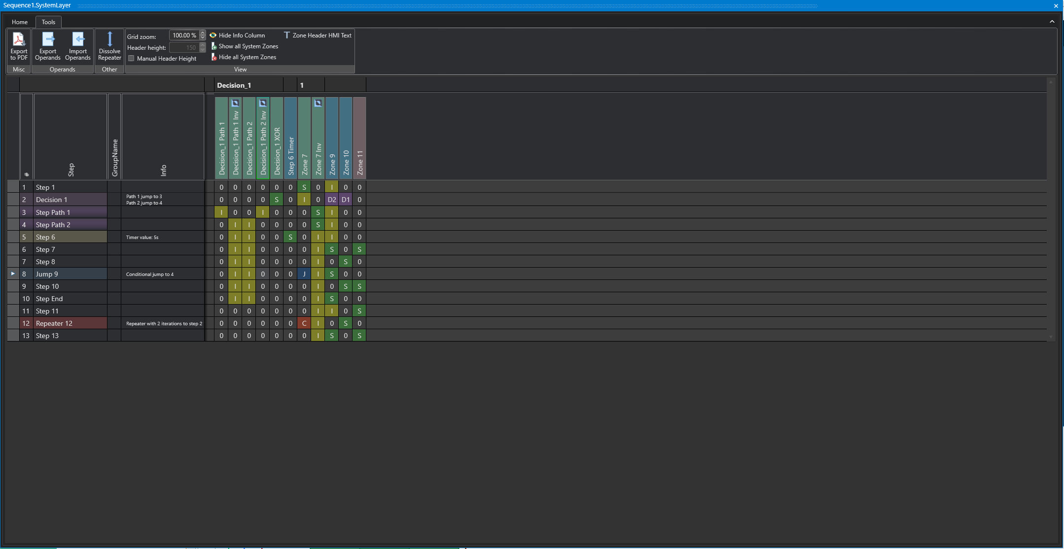
In the System Layer, the logical step sequence from the Logic Layer is connected with zones. The operands of the zones control and monitor the process flow. A separate system layer can be defined in each sequence. Thus, signals can be linked with zones from different Sequences.
Operands
'0' don't care
This means that the zone is not monitored.
If it is an output zone, the output is switched off.
'I' Interlock check
The interlock check is a function that monitors the state of the input signal linked to the zone. If the signal of the zone is not in the required state, the automatic operation of the sequence is interrupted.
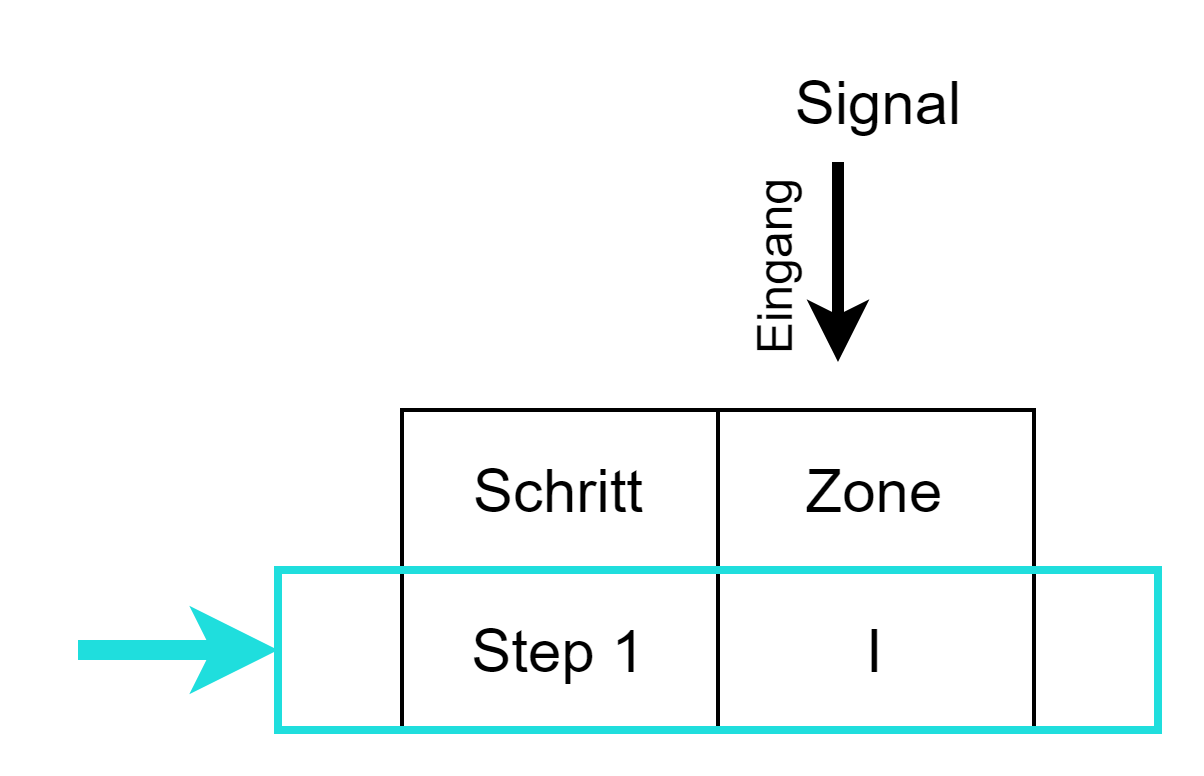
With the interlock check (operand I) the value of the signal linked to the zone is monitored. The value of the signal is true.
'S' Sequence Check
Sequence Check is a function that can be set in a step of a zone using the S operand. The Boolean value of the signal associated with the zone (input of the zone) is checked for a change of state. The signal can take the values 0 (false) or 1 (true). A change of state of the signal is called a transition and is the transition from 0 to 1, or false to true. As long as the transition is not executed, the condition for a step change remains false and the step remains active. When the transition is completed, the step increment condition becomes true, and the step counter is incremented. For Zone-InOut it is valid that with the Sequence Check the output is switched until the feedback is fulfilled. For Zone-Out, only the output is set and remains active until another zone's transition satisfies the step advance circuit. Zone-Out does not stop stepping in any case.
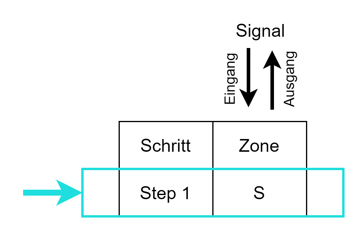
Sequence Check (Operand S) controls and monitors the transition of the signal associated with the zone. The value of the signal goes from 0 to 1, or false to true.
Inverted signal
Transitions from 1 to 0 of a signal can be checked by zones which use an inverted signal as input.
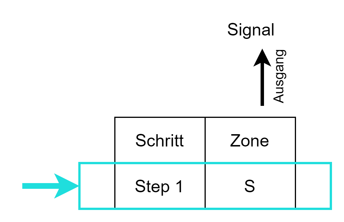
Input zone
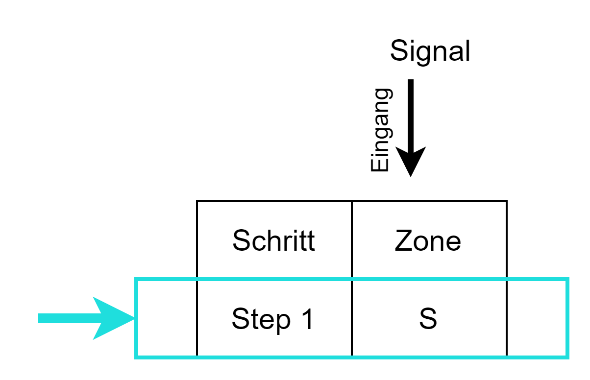
Waits for a change of state from logical 0 to 1.
Output zone
Used to set the output to logic 1.
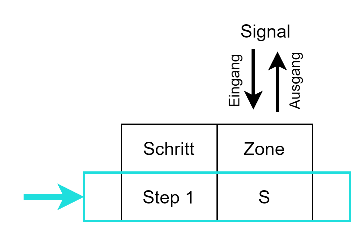
In-Out-Zone
An additional evaluation of the input zone takes place, the output remains active until the input zone becomes active.
'M' Monitoring check
Same function as 'Interlock check', but no interlock error is triggered and the automatic remains active.
The interlock is logged in the alarm history.
'D1' Decision Path 1
Provides the possibility to define one or more input zones, as condition for Path 1, in the Decision.
'D2' Decision Path 2
Provides the ability to define one or more input zones, as a condition for Path 2, in the Decision.
'J' Jump
Provides the ability to define one or more input zones, as a conditional jump variable, in the Jump step.
'C' Cancel
Used to define an input zone as a cancel variable for the repeater.
With the help of the operands, it is now defined in which step the system must have which state or which state the system must assume. By means of the Zone-InOut and Zone-Out is defined which outputs are switched in which step. This means that the defined states can also be the only valid ones. The system displays all other states of the system as errors and diagnoses the deviation from the target state.
Studio
Target/actual comparison
The bit-precise definition of the input and output signals enables a constant target-actual comparison of the system with the defined bit pattern for each process step; any deviation is detected and the deviation from the target state is displayed.
