A "Constantly Monitored Zone" CMZ in machines refers to an area or zone in a machine that is constantly monitored by sensors or other monitoring mechanisms. These zones can include, for example, critical components or processes of a machine where the occurrence of a fault or malfunction can have serious consequences. These zones can be monitored by various types of sensors, such as temperature or pressure sensors, which continuously measure the values in the zone and transmit them to the machine's control system. The control system can then take appropriate action to prevent or minimize potential problems if there are deviations from normal values.
Examples of Constantly Monitored Zones in machines include:
•The zone around the machining area in a CNC machine, where the temperature of the cutting tool and material being cut is constantly monitored to prevent overheating and damage.
•The zone around the burner in an industrial furnace, where the temperature and gas supply are constantly monitored to ensure firing quality and safety.
•The zone around the welding in a robotic welding machine, where the temperature and pressure of the welding equipment must be monitored to ensure consistent weld quality.
Overall, Constantly Monitored Zones on machines are an important part of safety and quality control to ensure smooth operation and protection of people and machines.
CMZs are found at the Plant, Hardware Zone and Sequence levels. The division into these levels determines which level is shut down when a fault occurs. If a fault occurs at the plant level, such as loss of compressed air, the automation of the entire plant is stopped. Errors on the hardware zone level lead to the stop of the respective hardware zone and errors in Sequences stop the respective Sequence. The errors are logged in the alarm history.
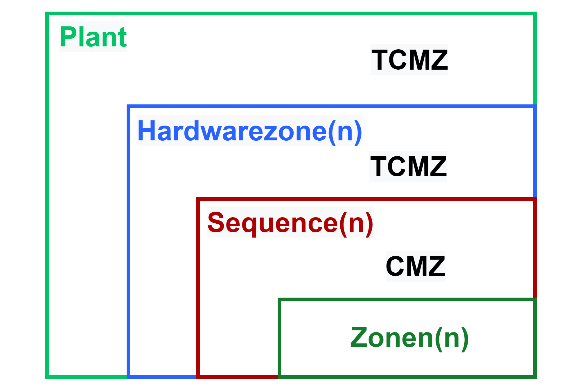
Depending on the level in which the CMZ was declared, a corresponding entry is created in the PLC code. This can be either at the Plant, Hardware Zone or Sequence level.
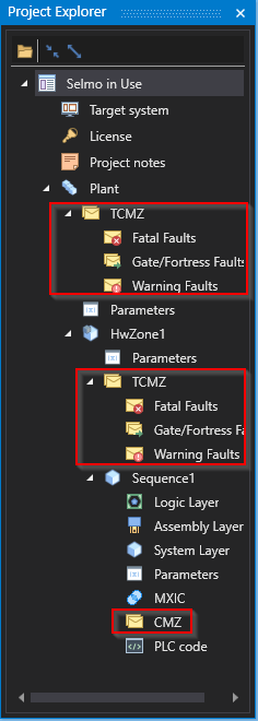
Studio
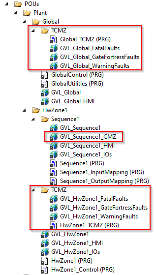
PLC
The CMZs are edited and created with the help of an editor. Thereby different options are provided, which are explained in the following:

Studio
Variable Name
The name of a variable is important for the readability and comprehensibility of the code. A good variable should be unique, meaningful, and functional. That is, it should have only one meaning, describe the content or purpose of the variable, and match the data type and logic of the program.
Notice:
Selmo uses the PLCopen Coding Guidelines. This is an internationally recognized standard for programming automation systems, especially programmable logic controllers (PLCs). The PLCopen Coding Guidelines establish rules and best practices to help developers ensure that their PLC programs are readable, reusable and robust. The guidelines cover a variety of topics, including variable naming, code commenting, program structure, and error handling. The naming of variables in the PLCopen Coding Guidelines follows certain rules. For example, variable names should be meaningful and reflect the purpose and type of the variable. The name should be written in English and follow certain conventions, such as the use of CamelCase. Furthermore, rules for naming input and output variables, temporary variables and constants are specified. Overall, the PLCopen Coding Guideline aims to improve the readability, maintainability and robustness of PLC programs and thus contribute to higher efficiency and productivity in the development of automation systems.
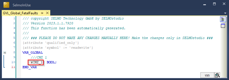
PLC
Variable Type
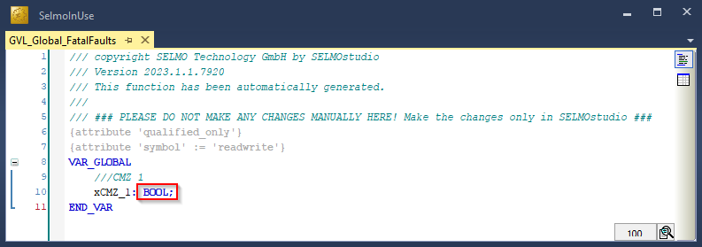
By default, the variable type is declared as a Boolean data type. However, the drop-down menu can be used to select the appropriate data type. The available data types correspond to the list of standard data types.
PLC
HMI Text
This text appears on the HMI when an error or warning occurs. It informs the user about the type and location of the problem. The text is displayed both in the Alarm Bar and on the Alarm Page of the HMI and serves as a comment of the variable in the PLC code.

HMI
Section
This is used to group and improve the clarity of the CMZ.

Studio
Inverted
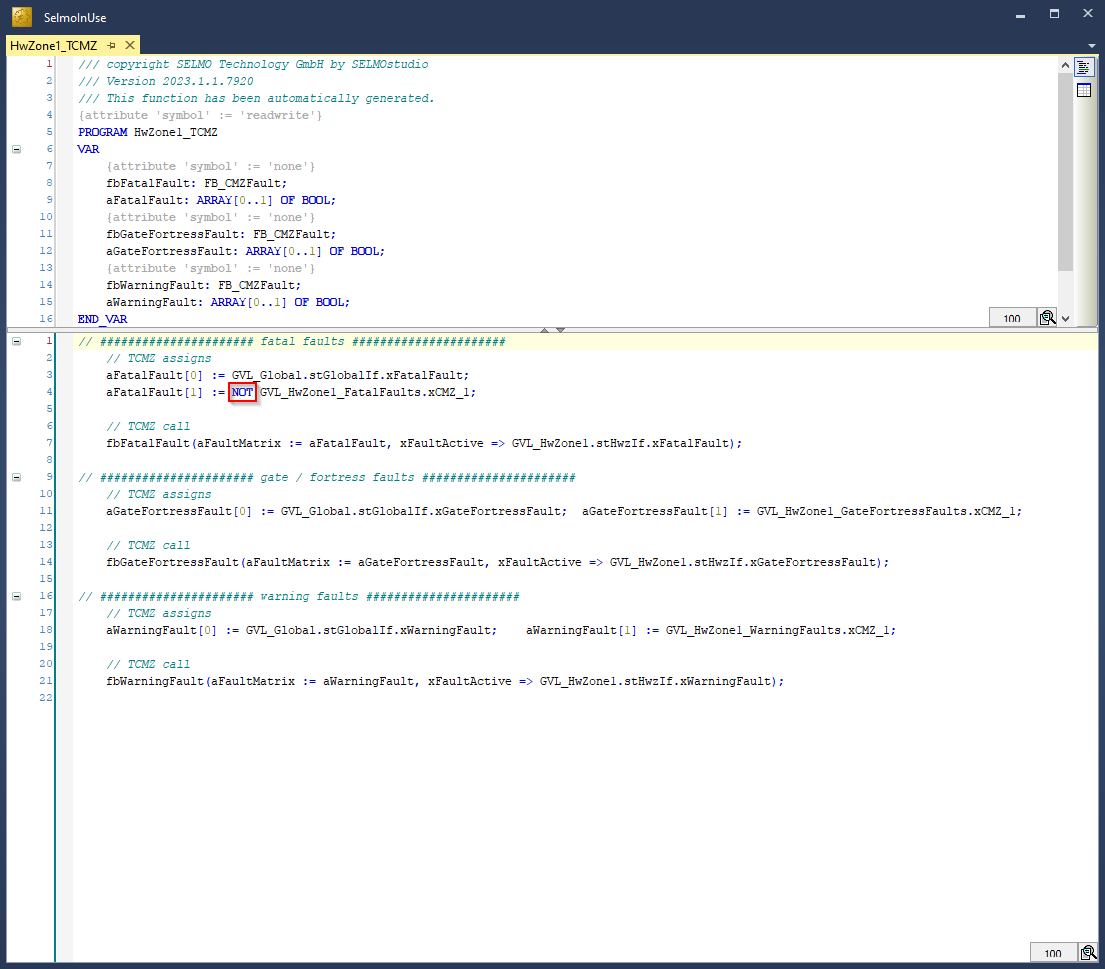
If the field "Inverted" is activated, the value of the linked variable is inverted in the PLC code of the corresponding level.
This is only possible with Boolean variable types.
PLC
Declaration as Input
If you declare the CMZ as "True", it will be declared as hardware input and included with the "AT %I*" attribute in the programming logic. This means that the variable receives a signal or value from a physical input of the system, such as a sensor or a switch.

PLC
HardwareInput
Prefix is added to the variable declaration in the generated PLC code.
Parameter
variables with a function (e.g. temperature maximum).
Parameter Mode
Selection between None, Greater Than, Less Than, Equals, GreaterEquals, LessEquals, NotEquals and Window.
Window Positive Parameter und Window Negative Parameter
A number is used to initialize this parameter.
To be able to select the window mode, the variable type must be something other than BOOL. Window is a comparison function and acts like a tolerance window. The window function can always be adjusted in the HMI. The Window Positive parameter is the maximum value and the Window Negative parameter is the minimum value.
Auto Reset (option only available in the sequence CMZ)
An Auto Reset in case of error refers to a function where an error is automatically reset without manual intervention. When an error occurs, it is automatically detected, and the system state is reset to the normal operating state. This feature is often used in automated systems to ensure that operation can continue without the need for an operator to manually intervene to correct the error. Error Auto Reset is particularly useful in critical applications where immediate intervention is required to minimize downtime or damage to equipment.
Error Delay [ms]
Used when the error should be triggered with a time delay. In summary, "Error Delay" is used as a term when an error occurs in signal processing and time delayed triggering is desired. The phenomenon where a signal briefly generates several fast pulses instead of a single pulse is referred to as "signal bounce" or also as "contact bounce".