The parameter levels of Plant, Hardware Zone and Sequence are frequently used in automation technology to enable a hierarchical structuring of parameters. The Plant level includes all parameters that are relevant for an entire plant or system. For example, parameters such as the operating mode or the overall performance of the plant are defined here. The hardware zone level refers to specific areas or components of the plant, such as a particular conveyor section or machine area. Here, parameters are defined that are only applicable to this area or component. The Sequence level refers to specific sequences or processes within the plant, such as the opening or closing of a valve. Here, parameters are defined that only apply to these particular sequences or processes. This hierarchical structuring of parameters enables clear and orderly management of parameters, which in turn facilitates maintenance and troubleshooting.
Parameter levels are one way to reduce the complexity of automated plants. They allow the plant to be divided into different areas, each with its own parameters. For example, a plant may consist of several hardware zones that have different sensors and actuators. Each hardware zone, in turn, can consist of multiple Sequences that control the plant's operations. For example, a Sequence can turn a sub-process on or off, control a temperature, or control part of a station. By using parameter levels, you can make the system clearer and easier to customize.
Parameter levels are divided as follows.
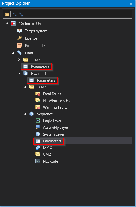
Studio
Plant level: The Plant level defines basic parameters that are relevant for the entire plant. These are settings and defaults that apply regardless of specific process steps or machines. Typical parameters defined at this level include, for example, temperature warnings that ensure that the plant operates within a certain temperature range. In addition, piece counters are also defined here, for example to monitor the number of products produced. Another important parameter at the plant level is recipes, which define the exact ingredients and quantity ratios manufacturing a product. By defining these basic parameters at the plant level, efficient and reliable production can be ensured.
Hardware Zone Level: At the Hardware Zone Level, parameters are defined that are specific to a particular machine area. Settings and defaults are defined here that apply only to this specific hardware zone and not to other parts of the plant. Typical parameters created at this level include display parameters that indicate the operation and status of the machine zone, such as temperatures, pressures, or flow rates. Another example of a parameter that affects the hardware zone is the recipes of the machine area. These are specific instructions that tell the machine what materials to use and in what quantities to produce a particular product. These recipes can be created and stored in the hardware zone to ensure the machine is consistent and efficient in producing products. Other parameters that could affect the hardware zone include configuring sensors, calibrating gauges, or setting safety parameters such as emergency stop switches or limits for temperatures and pressures. Overall, the creation of parameters in the hardware zone refers to the fine-tuning and configuration of machine areas to ensure optimal performance and efficiency while ensuring the safety of employees and equipment.
Sequence Level: The Sequence Level refers to the level of control elements that control the sequence of operations in a machine process. In this context, creating parameters relates to the settings that affect only the sequences within the Sequence. An example of a parameter at the Sequence level is the axis position. This means that the position of each axis of the machine system must be precisely defined so that the machine can perform the required movements and processes. These axis positions can be stored as parameters in the control level. Another example of a parameter at the sequence level is correction values. If irregularities occur during machine operation, correction values must be defined to compensate for them and optimize machine performance. For example, correction values can be set for temperature, pressure, or speed to ensure that the machine always operates within certain tolerances. The speed of the machine is another important parameter at the sequence level. The speed can be adjusted according to the requirements of the process to ensure that the machine produces the required output without being overloaded or having undesirable effects on the final product. In summary, parameters are set at the Sequence level to control and optimize specific functions of the machine system. These include axis positions, correction values, and speeds that help ensure that the machine process runs smoothly and accurately, and that the system's output is optimized.
Parameters set in a system or program can be used at all levels below. For example, if you think of a tree structure, the parameters set at the top level can be used at all levels below. However, if you try to use these parameters at a level higher than the original level, it will not work. A parameter is a specific setting made in a system or program. These settings can have various properties that can be edited. For example, these properties can be data type, value range, or default value. In summary, parameters are set in a system or program to define settings that can be used by different levels in the system or program. Each parameter has different properties that can be edited to change its functionality.
Depending on the level at which the parameter was declared, a corresponding entry is created in the PLC code and in the HMI. This can be done either at the Plant, Hardware Zone or Sequence level.
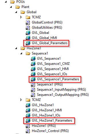
PLC
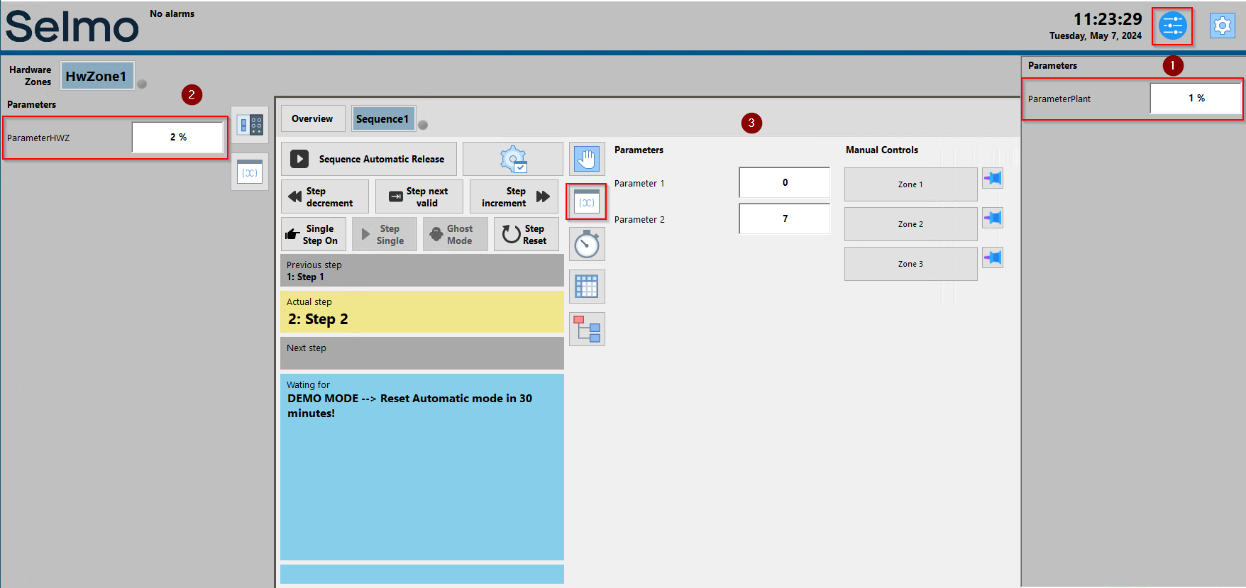
HMI
1. Plant level
2. Hardware zone level
3. Sequence level
The parameters are edited and created using an editor. Several options are provided, which are explained below:

Studio
Name
The name of the parameter is used as the basis for the variable name. The notation for the name of the parameter is freely selectable, but it is recommended to use a unique and descriptive name.
If the parameter is used as an input parameter for a zone, it is selected based on the layer and the parameter name.
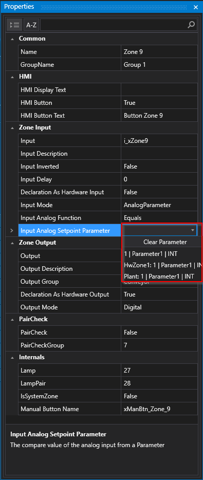
Studio
HMI Display Text
The display name of the parameter in the HMI refers to the name of the parameter shown on the HMI display of the system or machine. There is no special notation for the display name, but it is important that the parameter name is understandable and easy to read for the user.
However, for readability reasons, the amount of HMI display text should be kept to a minimum. This means that the display name of the parameter should be as short as possible, but still sufficiently meaningful to be quickly recognized and understood by the user.
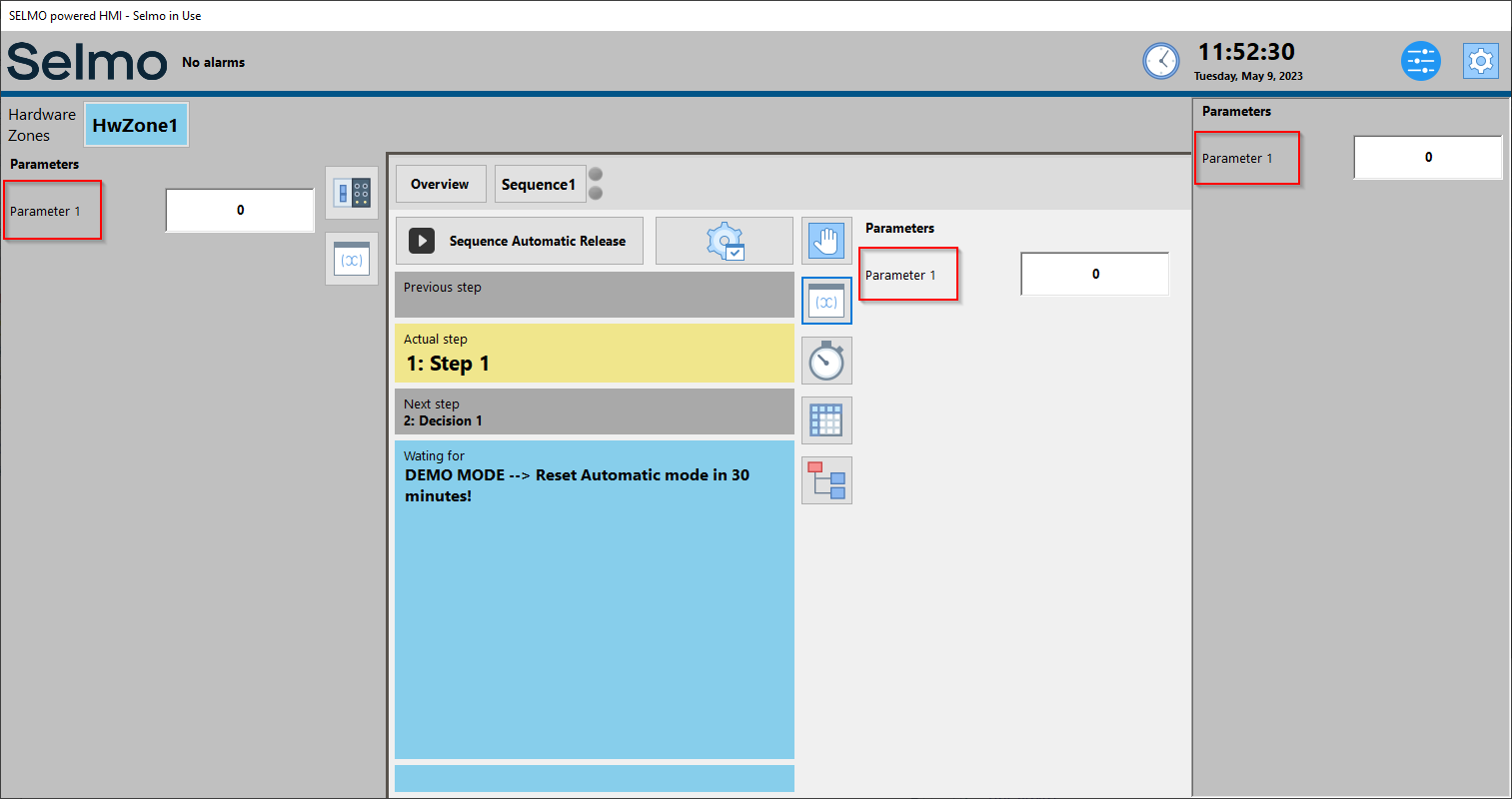
HMI
In addition, the display name of the parameter in the HMI also serves as a comment for the parameter's associated variable in the PLC code.
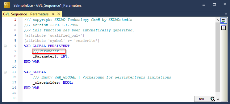
PLC
Variable Name
The variable name is automatically derived from the name of the parameter and is not editable. The name of a variable is important for the readability and comprehensibility of the code. A good variable should be unique, meaningful and functional. That is, it should have only one meaning, describe the content or purpose of the variable, and match the data type and logic of the program.
Tip:
Selmo uses the PLCopen Coding Guidelines. This is an internationally recognized standard for programming automation systems, especially programmable logic controllers (PLCs). The PLCopen Coding Guidelines establish rules and best practices to help developers ensure that their PLC programs are readable, reusable and robust. The guidelines cover a variety of topics, including variable naming, code commenting, program structure, and error handling. The naming of variables in the PLCopen Coding Guidelines follows certain rules. For example, variable names should be meaningful and reflect the purpose and type of the variable. The name should be written in English and follow certain conventions, such as the use of CamelCase. Furthermore, rules for naming input and output variables, temporary variables and constants are specified. Overall, the PLCopen Coding Guideline aims to improve the readability, maintainability and robustness of PLC programs and thus contribute to higher efficiency and productivity in the development of automation systems.
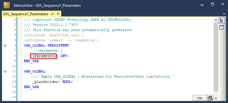
PLC
Type
The parameter type indicates whether the parameter is an input parameter or an output parameter. An input parameter is used to enter values into the system or make certain settings, while an output parameter is used to output values from the system or display certain information. An example of an input parameter could be a parameter that defines the desired position of a motor or a specific mode of operation. The user enters the value for this parameter, which is then used by the system. An example of an output parameter could be a parameter that indicates the actual position of a position encoder or provides a warning message when a certain condition is reached. In summary, the parameter type indicates whether the parameter is used to input or output values to control and monitor the system or machine.
PLC Data Type
The declaration of the variable type is done as integer data type by default. However, the drop-down menu can be used to select the appropriate data type. The available data types correspond to the list of standard data types.
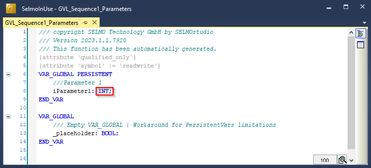
PLC
Initial Value
The initial value for a variable specifies the initial value that is assigned to the variable when the program is started or the parameter is reinitialized. Depending on the PLC data type, only certain input formats are permitted for the initial value. This means that the initial value for a variable must be entered in a specific format that matches the variable's data type.
Hint:
If the initial value is entered in an incorrect format, this can lead to malfunctions or errors in the program. It is therefore important to ensure that the initial value for a variable is entered in the correct format to ensure smooth functioning of the program. This is already checked in advance and displayed accordingly.

Studio
Unit
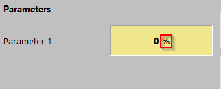
The display unit of the parameter in the HMI refers to the unit in which the parameter is shown on the HMI display of the system or machine. The unit may vary depending on the PLC data type, but all entries are valid and are not checked for correctness or consistency with other parameters or the system. However, it is important that the unit is understandable to the user and helps them to interpret the parameter correctly. A correct and unambiguous display unit can help to avoid misunderstandings and facilitate the operation of the system. Therefore, the parameter's display unit should be carefully chosen and properly documented to ensure correct understanding and error-free use of the system or machine.
HMI
LL (Limit Low)
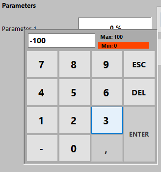
The minimum input value for an input parameter is the smallest value that is acceptable for that parameter. This value can vary depending on the PLC data type, and only certain input formats that match the parameter's data type are allowed. It is important to ensure that the minimum input value is entered in the correct format. Otherwise malfunctions or errors may occur in the program. For example, an incorrect input can lead to an overload of the system or an unexpected reaction. Therefore, the minimum input value should be carefully documented and entered to ensure correct operation of the system or machine. Suppose a value is entered for a parameter that is below the defined lower limit (LL), this limit is usually highlighted in red to indicate that the input is not accepted. The system or machine refuses to accept the value input to prevent the system from becoming faulty or unstable. The red marking alert the user to the error and helps them correct the input value accordingly.
HMI
LH (Limit High)
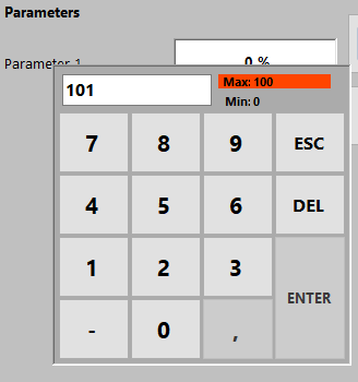
The maximum input value for a parameter is the highest value that is acceptable for that parameter. If a value is entered for a parameter that is above the defined upper limit (LH), this limit is usually highlighted in red to indicate that the input will not be accepted. Similar to an input value that is too low, the system refuses to accept the input of the value to prevent the system from becoming faulty or unstable. The upper limit value is important to ensure that the machine or system operates within safe and efficient operating parameters. Correct entry of the parameter is important to ensure system performance and safety. Therefore, the upper limit should be carefully documented and maintained to prevent the system from becoming faulty or unstable.
HMI
DD (Decimal Digits)
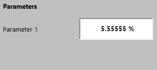
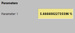
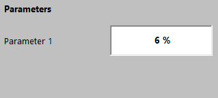
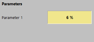
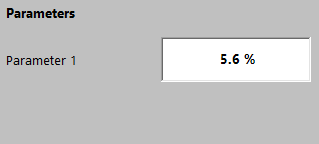
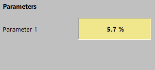
DD (Decimal Digits) stands for the number of decimal places to be included when displaying the parameter value. This number is usually defined in the parameter setup and may vary depending on the application. If the value of DD is set to 0, it means that no decimal places should be displayed, and the value is displayed as an integer. If DD is set to -1, no decimal places are considered, if DD is set to 1, one decimal place is considered and so on. The number of decimal places is important to ensure correct and accurate display of the parameter value. If the number of decimal places is insufficient, important information may be lost or displayed inaccurately. If the number of decimal places is too high, it may affect the readability of the value. Therefore, it is important to carefully define and monitor the number of decimal places to ensure accurate and readable representation of the parameter value.
DD -1 (Input/Output)
HMI
HMI
DD 0 (Input/Output)
HMI
HMI
DD 1 (Input/Output)
HMI
HMI
DP (Decimal Place)
DP (Decimal Place) refers to the position of the decimal point when displaying the parameter value. This value is usually defined in the parameter setup and indicates where the parameter value should be divided to indicate the decimal place. For example, setting the value of DP to 2 means that the parameter value will be divided at the second digit from the right to indicate the decimal place. For example, the value 12345 would be represented as "123.45". The position of the decimal point is important to ensure that the parameter value is displayed correctly and understandably. If the decimal point is placed in the wrong location, it can cause confusion or inaccurate information. Therefore, it is essential to carefully define and monitor the position of the decimal point to ensure clear and accurate representation of the parameter value.
Section
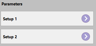
The Section property can be used to group parameters and display them in a common menu item in the HMI. When parameters are marked with the same Section property, they are automatically grouped together in the same group. Grouping parameters into sections makes the menu clearer and more user-friendly, as related parameters are grouped together, and the user can find and change them more easily. The Section property can be named anything to describe the group of parameters appropriately. An example of a useful naming of a Section property is "Communication Settings" for parameters related to the communication of the system. Using Sections can make parameter handling easier and more efficient, resulting in an overall improved user experience.
HMI
Disable Input in Automatic
The Disable Input in Automatic function makes it possible to disable the changing of input variables while the automatic mode is active. This means that users cannot manually change the value of an input variable while the system is operating in Automatic mode. This feature is particularly useful for ensuring the security and integrity of the system, as it prevents users from inadvertently interfering with the operation of the system while it is operating in an automated mode. When the automated mode is disabled, users can manually change the value of the input variables again. This feature is particularly useful in industrial applications where it is important that the system operates safely and reliably, even when operated by different users.
Hide
If the "Hide" field is set for a parameter, this parameter is not displayed in the HMI. This means that users cannot see or access the parameter even if it is in the system. This feature can be useful when a parameter is used only for internal purposes or to configure the system and users do not need to know that it exists. It can also help to make the user interface clearer by hiding unimportant or rarely used parameters. However, it is important to note that hiding a parameter does not mean that it is no longer present in the system. The parameter can still be used by other system components, and changes to its value can still affect the system.
Button mode
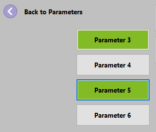
Boolean parameters can be created as buttons. Different modes are available:
"On": switches the parameter variable to true when the HMI button is pressed.
"Off": Switches the parameter variable to "false" when the HMI button is pressed.
"Switch": Switches the parameter variable to "true" when the HMI button is pressed and to "false" when the HMI button is released.
"Toggle": Switches the state of the parameter variable between "true" and "false" each time the button is pressed.
If the HMI button is in the green state, this corresponds to the 'true' value of the parameter variable. If the button is in the gray state, this corresponds to the 'false' value.
HMI
DHI (Declaration as Hardware Input)
Boolean value which is only used for Bekhoff target system/Twincat target system so that it can be linked directly to the IOs. The address declaration shows %I* if you check it.
DHQ (Declaration as Hardware Output)
Boolean value which is only used for Bekhoff target system/Twincat target system so that it can be linked directly to the IOs. The address declaration shows %O* if you check it.
Driver Input
Information about which parameters are linked to the driver. The connection with analog inputs or outputs is important. In some drivers, at the assembly level, if an analog input is present, it is possible to link this input directly to a parameter. The parameter that has been selected can then be read under the 'Driver Input' field.
Driver Output
Information about which parameters are linked to the driver. The connection with analog inputs or outputs is important. In some drivers, at assembly level, if an analog output is available, it is possible to link this output directly to a parameter. The parameter that was selected can then be read under the 'Driver output' field.