The Selmo Solution is a software solution that allowsto create and control processes of automated plants with a graphical user interface. To convert the Selmo Solution into PLC code that the plant can execute, you need to perform the following steps:
•Open the Selmo Solution in the Selmo Studio application.
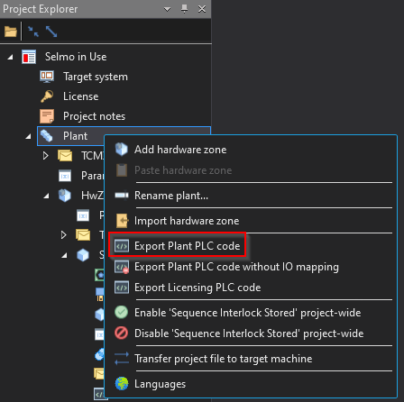
•Select the Plant you want to export by clicking on it in the Project Explorer.
•Right-click on the Plant and select the "Export Plant PLC Code" option from the context menu.
•Specify a name and location for the exported file and click "Save".
•The Selmo Solution will now be converted to PLC code and saved to the specified file.
Hint:
With Selmo, the possibility has been created to generate a PLCopen-compliant XML by using an export function and importing it into the selected controller. This means that the program, libraries, and projects created with IEC 61131-3 can be saved in a standardized XML format that can be read and edited by various software tools. The PLCopen XML format is part of the IEC 61131 series of standards and is to as IEC 61131-10. It provides an open interface for exchanging information between development environments and other platforms. The PLCopen XML format is described in the PLCopen technical documentation.
Studio
You can then open the exported file in your preferred PLC programming environment and transfer it to the plant.
PLC
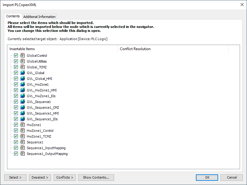
This PLC program contains the following elements that are necessary for control and diagnostics:
The Plant elements are the basic building blocks for configuring and controlling the plant. They have the following properties:
•They act GLOBALLY, that is, they affect all hardware zones and all licensed functions of the plant.
•Global Control is an element that enables general calling of hardware zones and licensing.
•Global Utilities is an element that provides some functional elements useful for diagnostics and maintenance of the installation. For example: Lamp Test, Global Release, Global Reset, etc.
•The plant has a Global TCMZ (Total Constantly Monitored Zone) system that constantly monitors all the important parameters of the plant, such as the compressed air or lubricant supply. The Global TCMZ system acts on all hardware zones of the plant and can interrupt the automation in any hardware zone in case of fault detection. This increases the safety and efficiency of the plant.
•GVL_Global_* is an important resource for programming plants with different elements. It allows us to define and manage globally the variables needed for the function and control of the elements. This allows the elements to communicate with each other and exchange data. The GVL_* contains the names, types, and values of the variables assigned to the elements.
The hardware zones are necessary to control and monitor the individual machine areas. They make it possible to switch between manual and automatic operating modes and to execute the defined sequences.
•<HwZone1> is an element that calls and controls all sequences in the hardware zone.
•<HwZone1>_Control is an element that provides additional functions such as mode selection, EOC mode or status information of the Sequences.
•<HwZone1>TCMZ is an element that constantly monitors the hardware zone and interrupts the automatic in case of an error.
•GVL_<HwZone1>_* is an important resource for programming machine zones with different elements. It makes it possible to globally define and manage the variables needed for the function and control of the elements. This allows the elements to communicate with each other and exchange data. The GVL_* contains the names, types and values of the variables associated with the elements.
Attention:
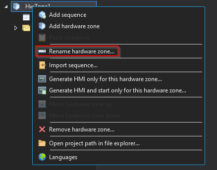
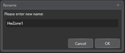
Renaming the hardware zone changes the name<HwZone1> of the entire structure including the Global Variable List, PLC program and HMI (see PLC code).
Studio
Studio
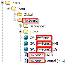
PLC program
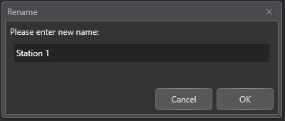
Studio
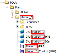
PLC Program
The Sequence elements describe the sequences and processes within a hardware zone. Any number of Sequences can be defined in a hardware zone and always consist of the following elements:
•<Sequence1> is the basis of a logical process sequence and is divided into the following sections:
Standard Beginning
Sequence Logic Control
CMZ
Standard End
•In the <Sequence1>_InputMapping, input signals of the real world are assigned to the sequence.
•In the <Sequence1>_OutputMapping, output signals are assigned to the real world of the sequence.
•GVL_<Sequence1>* is an important resource for programming logical process sequences with various elements. It allows us to define and manage globally the variables needed for the function and control of the elements. This allows the elements to communicate with each other and exchange data. The GVL_* contains the names, types and values of the variables assigned to the elements.
Attention:
Renaming the Sequence changes the name<Sequence1> of the whole structure including the global variable list, PLC program and HMI (see PLC code).
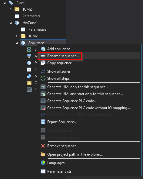
Studio
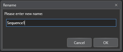
Studio
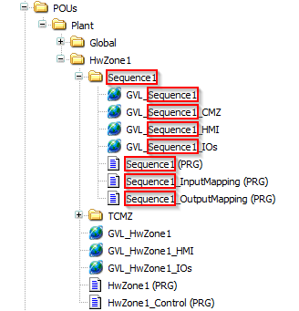
PLC program
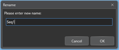
Studio
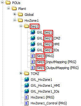
PLC program
After exporting the PLC code of the entire Plant, an HMI can be generated which has the same structure as the PLC program:
- Plant: This is the top level representing the entire plant. Here the user can get an overview of the plant's status and performance.
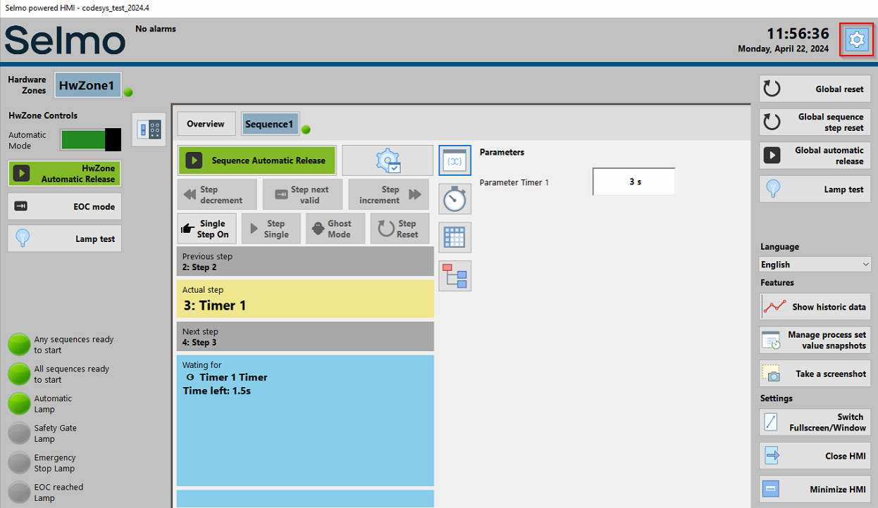
HMI
- Hardware Zones: These are the lower levels representing the different areas of the plant. Here the user can control and monitor the individual components and devices of the plant.
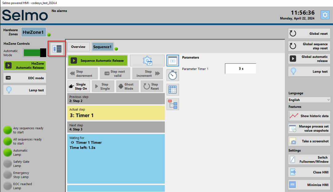
HMI
- Sequence: This is the lowest level, which describes the sequences and processes of the plant. Here the user can start, stop, pause, and modify the sequences required for the production or operation of the plant.
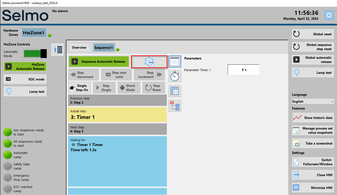
HMI