The Zone-In can be used to process input information from e.g., sensors. If the Sequence check is set in a Zone-In in a step, a state change of this Zone-In is expected for this step. An interlock check of an input zone ensures that the expected state of this zone-in this step is maintained. In practice, for example, a switch can be monitored by a Zone-In. If a switching operation is required, the signal of the switch must be linked to the Zone-In and a sequence check must be set in the corresponding step.
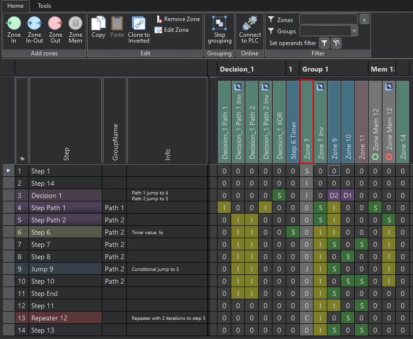
Create Zone-In
To create a Zone-In, click on the corresponding icon.
Studio
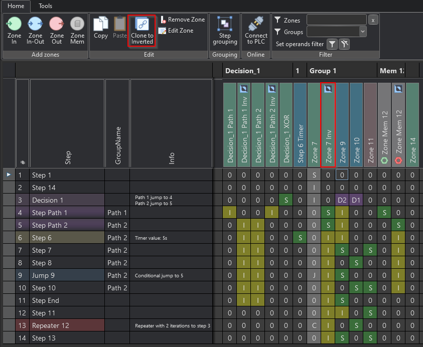
Inverted Zone-In
To completely protect a signal, an inverted Zone-In can be inserted. The inverted zone monitors the safe transition of the signal associated with the zone from true to false. For example, pushbuttons, sensors, etc., are monitored with it. This can be used to prevent incorrect operation. The button Clone to inverted inserts an inverted zone of the selected Zone-In.
Studio
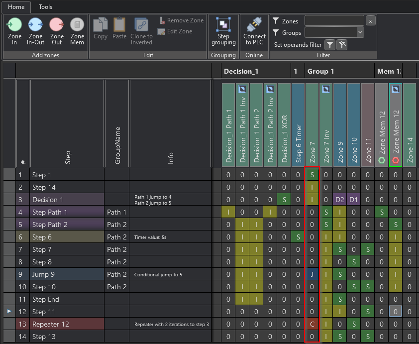
Operands of the Zone-In
If a zone-in is to be monitored in the step, it is necessary to enter the operand 'I'. The operand 'S' is used to wait for a change of state of the zone. The Zone-In is used to process input signals like buttons, sensors etc.
Studio
Assignment of signals to the Zone-In
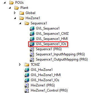
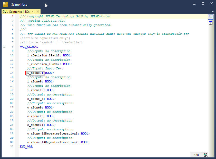
Further the input of the Zone-In is generated in the code and can be linked to a signal, see code below:
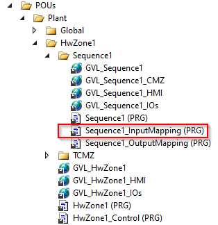
PLC
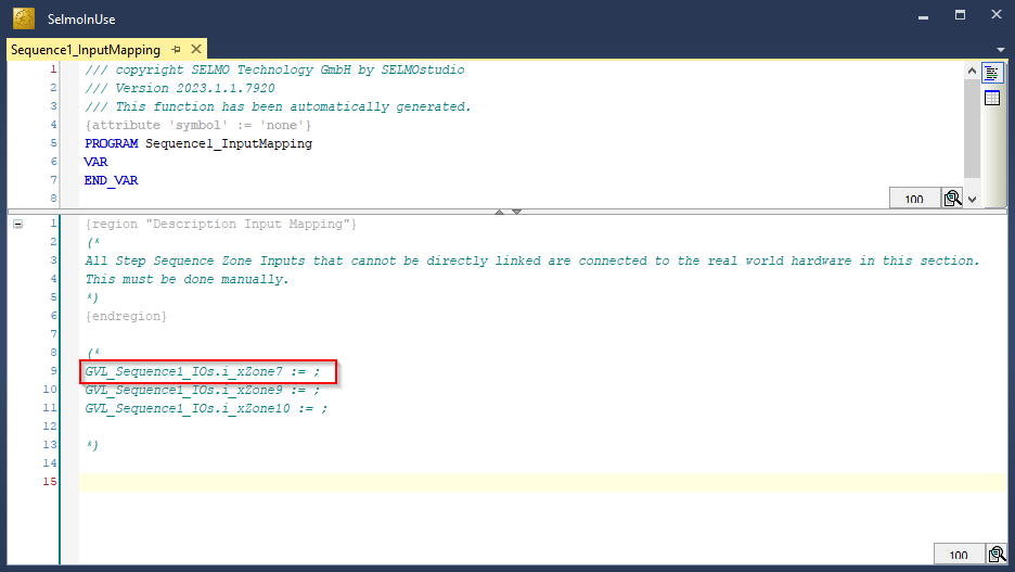
PLC
Properties
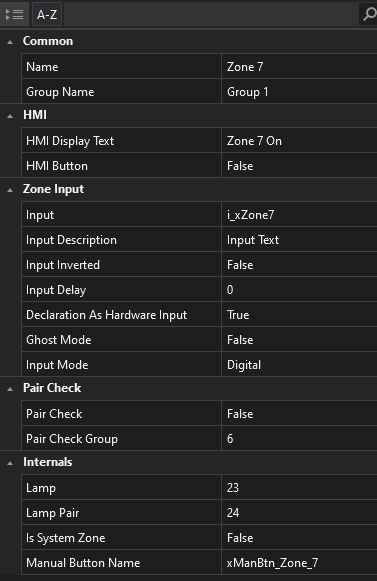
Studio
Name
The name serves as an identifier of the zone and is displayed in both the HMI and the system layers.
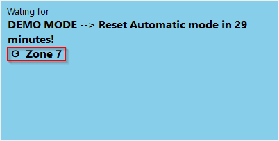
HMI
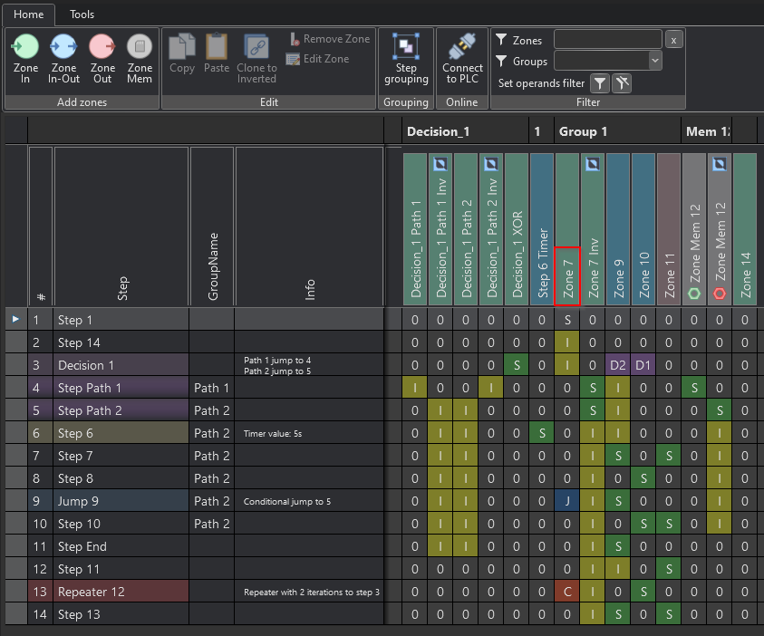
Studio
Group Name
The GroupName property can be used to group zones together. It also serves as a filter name for the filter function.
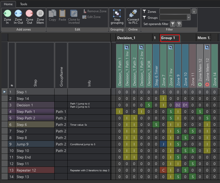
Studio
HMI Display Text
If a text is entered here, the text is only effective in the HMI and is adopted as the display text. The property Name is overwritten in the HMI.
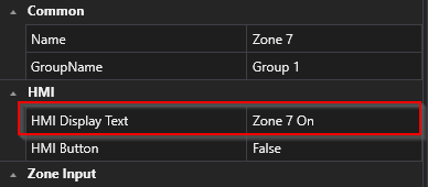
Studio
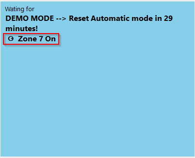
HMI
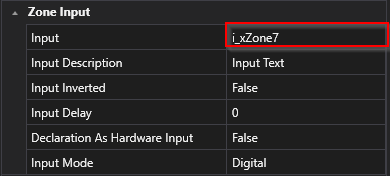
Input
In the context of PLC programming, the term "input variable name" refers to the designation or name of an input variable that is defined and used in the programmable logic controller (PLC) program code. For example, an input variable may be a signal from a sensor or other source that is processed by the PLC to perform a specific action. The name of the input variable in the PLC program is an important aspect of controller programming because it helps make the code easier to read, understand, and maintain. Therefore, the name should be carefully chosen and descriptive to clarify the function of the input variable and increase the readability of the code.
Studio
PLC
PLC
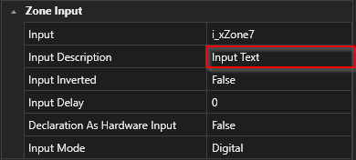
Input Description
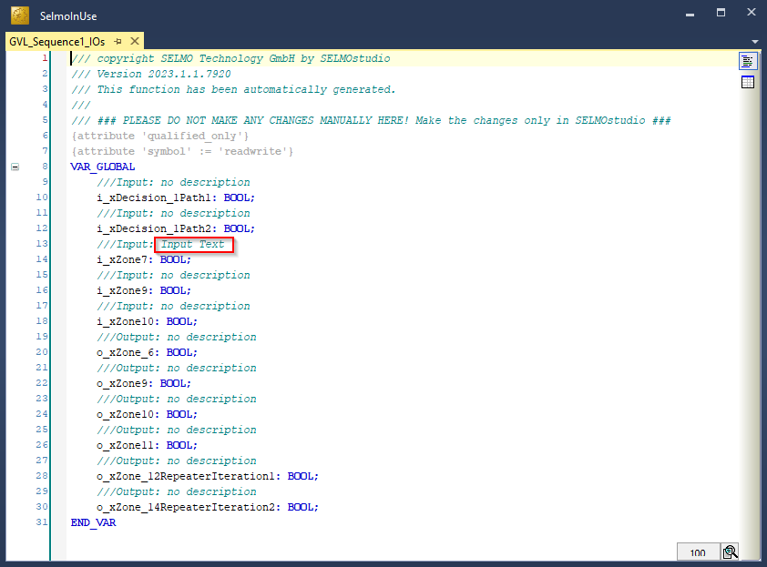
In PLC programming, it is important that each input variable in the code has a meaningful description. Such a description helps other programmers or maintenance personnel to understand and edit the code more easily. The input variable description should ideally describe the purpose and operation of the variable.
A clear and concise description of the input variable can also ensure that it is properly configured and calibrated before it is integrated into the PLC program. It also aids in debugging and troubleshooting the code by allowing the programmer to quickly determine which input variables are affected. The input variable description should therefore be considered an important part of the PLC program documentation to increase code efficiency, maintainability, and accuracy.
Studio
PLC
Input Inverted
Please specify whether the input signal is inverted or not. This means that you need to decide whether the signal entering a particular system is inverted in polarity or not. An inverted signal polarity means that the signal is reversed in terms of its positive and negative polarity. It is important to make this decision because it affects the way the signal is processed in the system.
Input Delay
Please specify by how many milliseconds the input signal should be delayed. The delay refers to the time difference between when the signal is received and when it is processed in the system. A delay may be intended to modify the signal in a particular way or to ensure it is processed synchronously with other signals. The exact amount of time to delay the signal depends on the requirements of the system and the type of signal being processed.
Declaration as Hardware Input
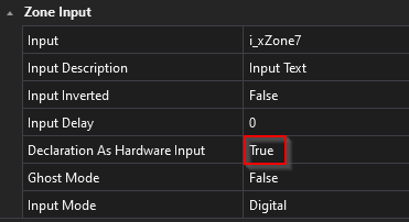
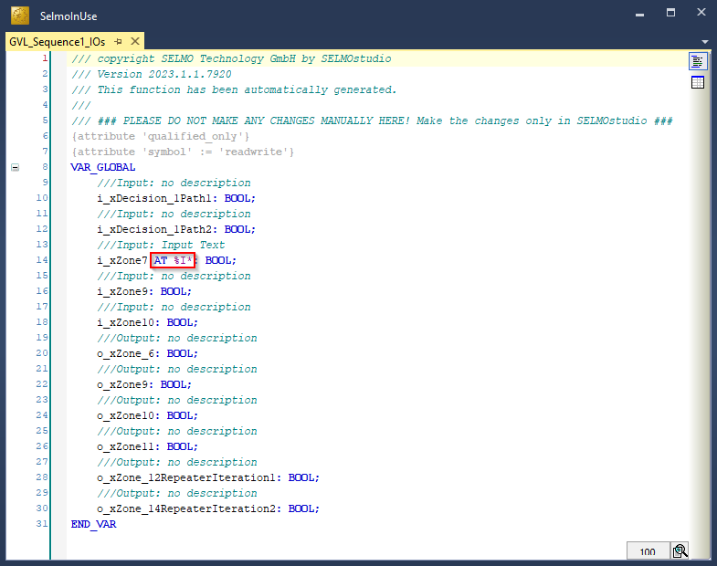
If you declare the input as true, it will be declared as hardware input and included with the "AT %I*" attribute in the programming logic. This means that the variable receives a signal or value from a physical input to the system, such as a sensor or switch.
Studio
PLC
Input Mode
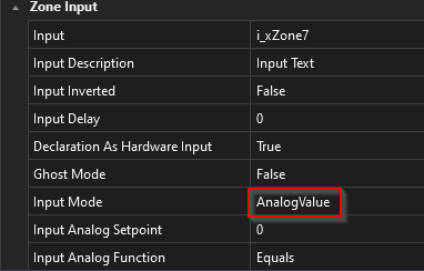
The type of signal is determined by the mode of the input. This can be either a digital or analog signal or a parameter. The mode of the input thus specifies what kind of signal is expected and how this signal should be interpreted. For example, if the input mode is set to "digital", the system expects a signal consisting of discrete values, while a continuous signal is expected in an analog input mode. In parameter mode, on the other hand, a value representing a specific parameter is expected. Overall, the type of signal that a system receives, and processes thus depends largely on the set input mode.
AnalogValue
If 'AnalogValue' is selected, the zone waits internally for a digital signal while an analog value is selected externally. Forwarding takes place as soon as this function is activated and a specific condition is met. This function can be found in the PLC code under the corresponding zone.
AnalogParameter
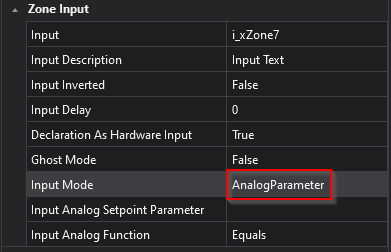
The principle corresponds to that of 'AnalogValue', but the analog step differs in that it is no longer a static value, but a parameter. The corresponding name of the selected parameter is then displayed under 'Input Analog Setpoint Parameter'. This function can also be found in the PLC code under the corresponding zone.
ParameterList
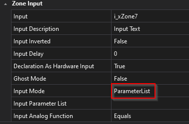
The 'ParameterList' is compared with an input signal, whereby an analog value is read in again. The difference, however, is that several comparisons can be carried out per step. To be able to use this function, a parameter list must already exist or be created so that it can be selected in the desired zone. The selected parameter list is then in 'Input Parameter List'. Wherever you want to make a comparison in the parameter list, a 'Sequence Check' must be set in the system layer.
ParameterInput
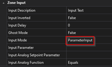
With this function, the input signal is omitted; instead, two parameters are compared with each other. In the PLC code, the IO location of the zone is no longer used under the corresponding zone, but a parameter is also specified here.
PairCheck
When PairCheck is active, the zone is checked with other zones to ensure that certain conditions are met, such as the presence of signal 1 and signal 2, which must not occur simultaneously.
PairCheckGroup
The PairCheckGroup number is used to specify whether a zone-in a check should be grouped with other zones in the same group. This grouping allows certain checks to be applied to multiple zones that have the same PairCheckGroup number to ensure that the results are consistent.
Internals
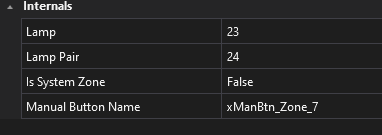
Lamp
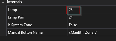
'Lamp' refers to the index of the respective array. The zone information is stored in the array via this index. This index is then used to access the array via the HMI and the texts are displayed in the 'Waiting for' window.
LampPair
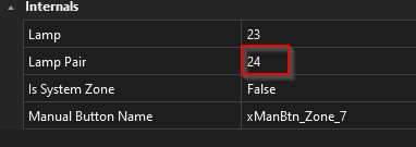
Same function as 'Lamp'.
Is System Zone
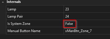
If the function is set to True, this serves as an indicator that it is a system zone that is created automatically (e.g. timer).
ManualButtonName
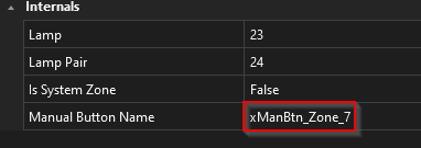
This is text-based information on how the manual button was named in the PLC.
