The Zone-InOut combines an input and output zone. To control the output, it is necessary to enter the operand 'S', so the output of the zone is controlled until the input of the zone reports the logical value 1. With this the condition is fulfilled and it can be switched to the next step. If the input of the zone is to be monitored, this is possible by entering the operand 'I'. For example, a valve of a pneumatic cylinder is controlled with the output of the zone and the end position of the cylinder is monitored with the corresponding input of the zone.
Create Zone-InOut
To create a Zone-InOut, click on the corresponding symbol.
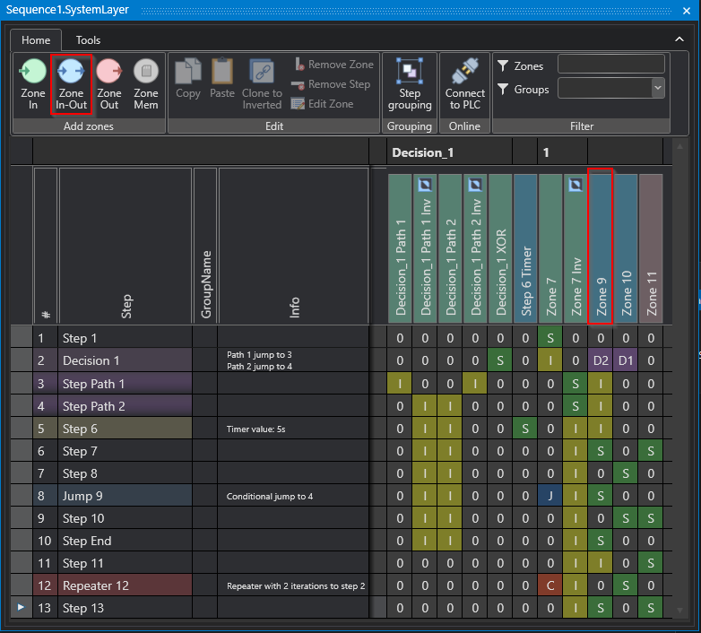
Studio
Operands of the Zone-InOut
The Zone-InOut is defined as an output with corresponding feedback via an input. Thus, outputs can be controlled until corresponding feedback is reported via the input. For example, a valve with position detection can be controlled by this. The position detection of the valve is designed in such a way that the position open or closed can be detected. To start the action (open valve), a sequence check is set. Now the output of the valve linked to the Zone-InOut is controlled until the target position of the valve is reached and the feedback is given via the linked input of the position detection. The interlock check can be used to check whether the inputs linked to the Zone-InOut remain in this state. If a "don't care" is set over the value 0 of the operand in a Zone-InOut, information of the linked input is ignored, and the linked output is not used.
If a Zone-InOut is to be monitored in the step, it is necessary to enter the operand 'I'. With the operands 'S' a change of state from logical 0 to logical 1 is waited for. The Zone-InOut is used to process input signals and output signals such as cylinders, frequency converters, contactors etc.
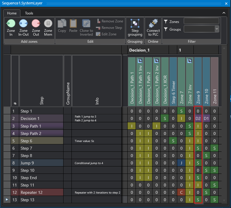
Studio
Assignment of signals to the Zone-InOut
Further the input of the Zone-InOut is entered in the code and can be linked to a signal, see following code:
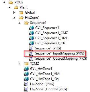
PLC
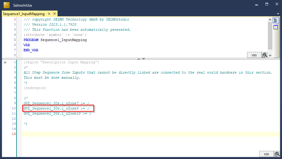
PLC
Furthermore, the output of the Zone-InOut is entered in the code and can be linked to a signal, see the following code:
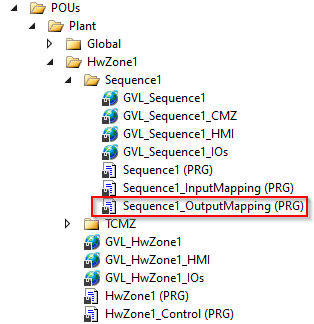
PLC
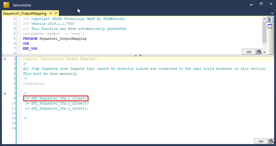
PLC
Properties
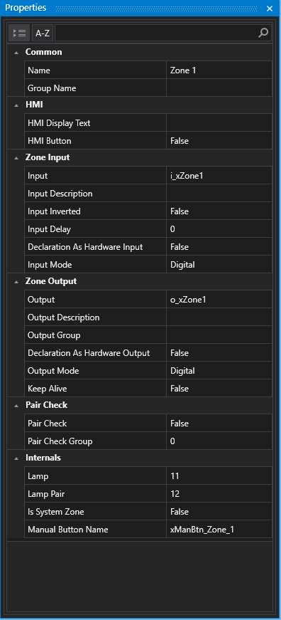
Studio
•Name, Group Name, HMI Display Text, HMI Button, HMI Button Text, Input, Input Description, Input Inverted, Input Delay, Declaration as Hardware Input, Ghost Mode, Input Mode, Keep Alive, Output, Output Description, Output Groub, Declaration as Hardware Output, Output Distribution, Output Distribution Stored, PairCheck, PairCheckGroup, Lamp, Lamp Pair, Is System Zone, Manual Button Name
See Zone-In
HMI Button
The HMI Button is a user interface that functions only in Manual mode and is used to control the output. Unlike the automatic mode, where the system operates automatically, the manual mode gives the user the ability to make manual interventions.
The HMI button is pressed to control the output until a feedback signal (input of the zone) becomes active. The feedback signal provides feedback to the system as to whether the desired state has been achieved or if changes need to be made. When MXIC cross-locking is active, the output cannot be controlled, and the HMI displays information about the zone with which the interlocking is taking place.
MXIC cross-locking is a safety function that prevents the zone from being activated unless certain conditions are met (zones x y are in a defined state). This is especially important in critical applications where the simultaneous occurrence of multiple events can lead to dangerous situations. Using the HMI button combined with the MXIC cross-lock ensures that only the desired output is activated and potential hazards are avoided.
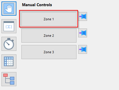
HMI
HMI Button Text
The HMI Button Text is the identifier of the zone's manual operation button and provides a clear functional designation of the zone to provide intuitive operation for the user.
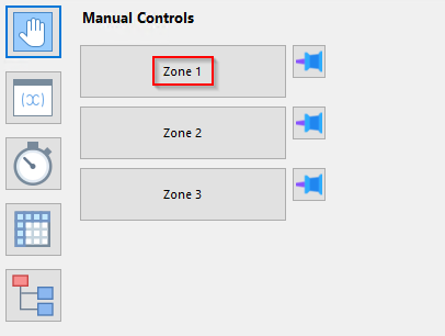
HMI
Output
In the context of PLC programming, the term "output variable name" refers to the designation or name of an output variable defined and used in the programmable logic controller (PLC) program code. For example, an output variable may be a signal from an actuator or other sink that the PLC processes to perform a specific action. The name of the output variable in the PLC program is an important aspect of controller programming because it helps make the code easier to read, understand, and maintain. Therefore, the name should be carefully chosen and descriptive to clarify the function of the output variable and increase the readability of the code.
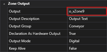
Studio
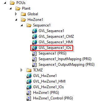
PLC
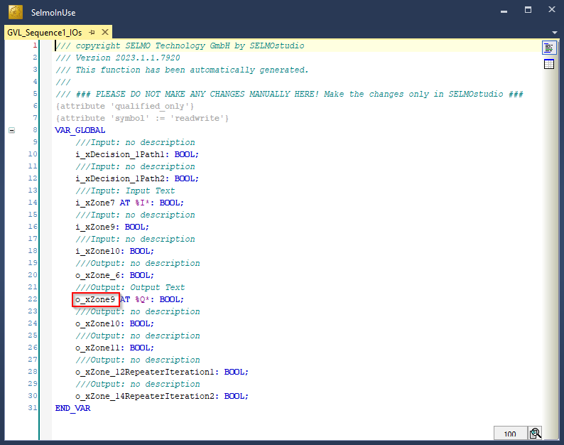
PLC
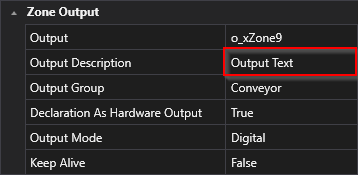
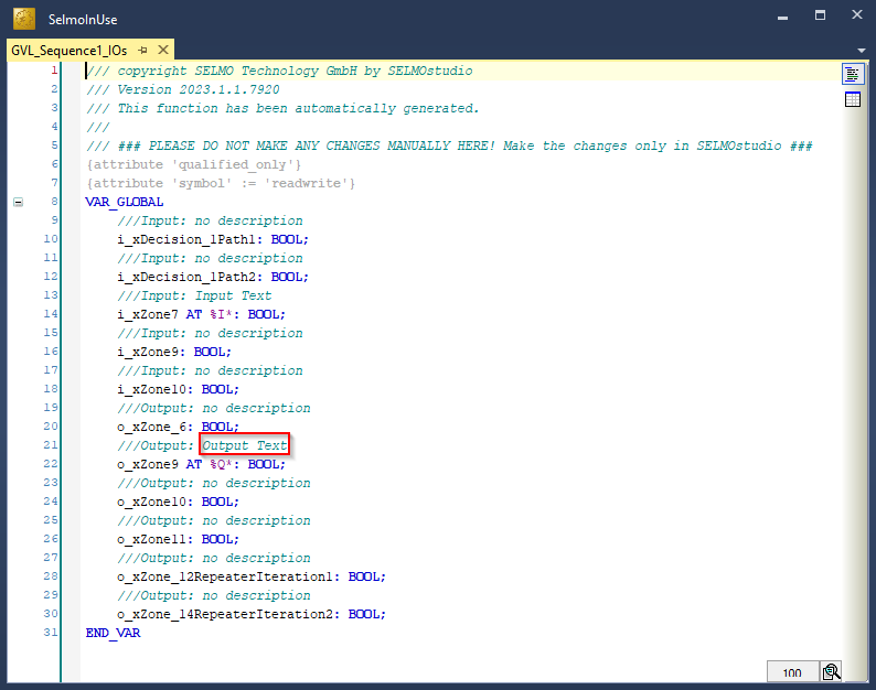
Output Description
In PLC programming, it is important that each output variable in the code has a meaningful description. Such a description helps other programmers or maintenance personnel to understand and edit the code more easily. The output variable description should ideally describe the purpose and operation of the variable.
A clear and concise description of the output variable can also ensure that it is properly configured and calibrated before it is integrated into the PLC program. It also aids in debugging and troubleshooting the code by allowing the programmer to quickly determine which output variables are affected. Therefore. the output variable description should be considered an important part of the PLC program documentation to increase code efficiency, maintainability and freedom from errors.
Studio
PLC
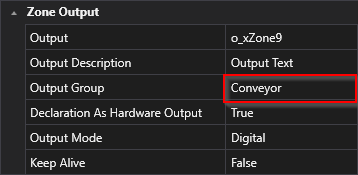
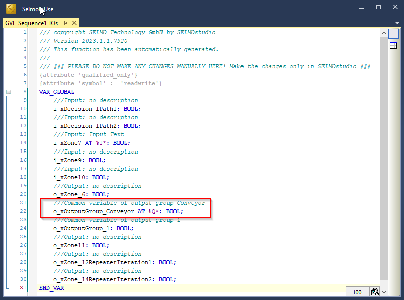
Output Group
The output group function enables the connection of several zones of the same type. Here, only one common output is used for all zones within the group. This means that if you combine several zones into one group, all these zones will control one output.
Studio
PLC
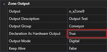
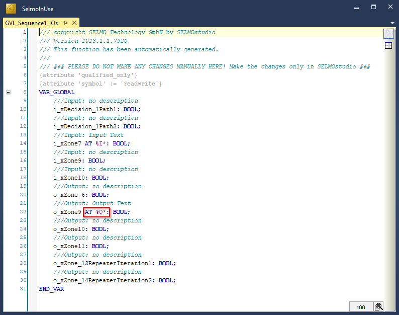
Declaration as Hardware Output
If you declare the output as "true", it will be declared as hardware output and included with the "AT %Q*" attribute in the programming logic. This means that the variable sends a signal or value on a physical output of the system, such as from a valve or an inverter.
Studio
PLC
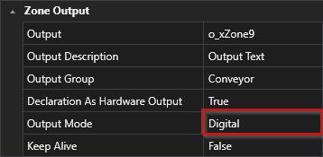
Output Mode
Studio
The type of signal is determined by the mode of the output. This can be either a digital or analog signal or a parameter. The mode of the output thus specifies what type of signal is expected and how this signal should be interpreted. For example, if the output mode is set to "digital", the system will send a signal consisting of a discrete value, while an analog output mode will send a continuous signal. A parameter mode, on the other hand, sends a value that represents a specific parameter. Overall, the type of signal that a system receives, and processes depends largely on the output mode that is set.
Output Distribution

This function copies a value to another parameter. The output value from Zone is assigned to the parameter. The output value can be used as required in the program.
Output Distribution Stored

Only valid if the output has been set. After the sequence check of the zone, the output distribution value remains the same.
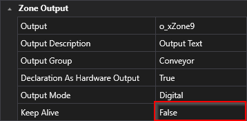
Keep Alive
Studio
Controlling the output offers two different approaches, which are determined by the "Keep-Alive" property:
![]()
•If the "Keep-Alive" property is set to the value "False", the default approach is to control the output. In this case, the output is automatically disabled once the feedback(input) is reached.
•If, on the other hand, the "Keep Alive" property is set to the "True" value, the output is controlled independently of the feedback. This means that the control of the output does not depend on the feedback, and it remains active regardless of the feedback.